
GSZ16 Service Manual

SERVICING
115
S-120 REFRIGERANT PIPING
The piping of a refrigeration system is very important in relation
to system capacity, proper oil return to compressor, pumping
rate of compressor and cooling performance of the evaporator.
POE oils maintain a consistent viscosity over a large tempera-
ture range which aids in the oil return to the compressor;
however, there will be some installations which require oil
return traps. These installations should be avoided whenever
possGible, as adding oil traps to the refrigerant lines also
increases the opportunity for debris and moisture to be
introduced into the system. Avoid long running traps in
horizontal suction line.
S-201 CLEANING ALUMINUM COILS
This unit is equipped with an aluminum tube evaporator coil. The
safest way to clean the evaporator coil is to simply flush the coil
with water. This cleaning practice remains as the recommended
cleaning method for both copper tube and aluminum tube resi-
dential cooling coils.
An alternate cleaning method is to use one of the products listed
in the technical publication TP-109 (shipped in the literature bag
with the unit) to clean the coils. The cleaners listed are the only
agents deemed safe and approved for use to clean round tube
aluminum coils. TP-109 is available on the web site in Partner
Link > Service Toolkit.
NOTE: Ensure coils are rinsed well after use of any chemical cleaners.
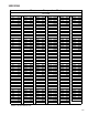
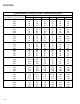
S-202 DUCT STATIC PRESSURES AND/OR STATIC PRES-
SURE DROP ACROSS COILS
This minimum and maximum allowable duct static pressure for
the indoor sections are found in the specifications section.
Tables are also provided for each coil, listing quantity of air
(CFM) versus static pressure drop across the coil.
Too great an external static pressure will result in insufficient air
that can cause icing of the coil. Too much air can cause poor
humidity control and condensate to be pulled off the evaporator
coil causing condensate leakage. Too much air can also cause
motor overloading and in many cases this constitutes a poorly
designed system.
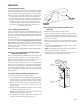
S-203 SINGLE PIECE AIR HANDLER EXTERNAL STATIC
To determine proper airflow, proceed as follows:
1. Using a Inclined Manometer or Magnehelic gauge , measure
the static pressure of the return duct at the inlet of the air
handler, this will be a negative pressure (for example-.30"wc)
2. Measure the static pressure of the supply duct at the outlet
of the air handler, this should be a positive pressure (for
example .20"wc).
3. Add the two readings together (for example -.30"wc + .20"wc
= .50"wc total external static pressure.
NOTE: Both readings may be taken simultaneously and read
directly on the manometer if so desired.
4. Consult proper air handler airflow chart for quantity of air
(CFM) at the measured external static pressure.
+ .20” wc
- .30” wc
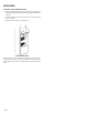
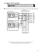
S-203A TWO PIECE AIR HANDLER EXTERNAL STATIC
PRESSURE
To determine proper airflow, proceed as follows:
1. Using a Inclined Manometer or Magnehelic gauge, measure
the static pressure between the outlet of the evaporator coil
and the inlet of the air handler, this will be a negative pressure
( for example -.30"wc)
2. Measure the static pressure of the supply duct at the outlet
of the unit, this should be a positive pressure (for example
.20"wc).
3. Add the two readings together (for example -.30"wc + .20"wc
= .50"wc total static pressure.
NOTE: Both readings may be taken simultaneously and read
directly on the manometer if so desired.
4. Consult proper air handler airflow chart for quantity of air
(CFM) at the measured external static pressure.
Supply Static
+ .20” wc
Return Static
- .30” wc