
Installation Manual
8
3. The difference between the measured saturated
condensing temperature and the liquid line temperature
is the liquid Subcooling value.
4. TXV-based systems should have a Subcooling value
of 6°F +/- 1°F.
5. Add refrigerant to increase Subcooling and remove
refrigerant to decrease Subcooling.
NOTE: Units matched with indoor coils equipped with a
TXV should be charged by Subcooling only. Superheat
can also be utilized to best verify charge levels with an
adjustable TXV and make adjustments when needed
in unique applications due to refrigerant line length,
differences in height between the indoor and outdoor unit
and refrigerant tubing sizes. These adjustments should
only be performed by qualied service personnel.
advance adjuStment recommendatIonS
1. Clamp a pipe clamp thermometer near the suction line
service valve at the outdoor unit.
a. Ensure the thermometer makes adequate contact
for the best possible readings.
b. The temperature read with the thermometer should
be higher than the saturated suction temperature.
2. The difference between the measured saturated suction
temperature and the suction line temperature is the
Superheat value.
3. TXV-based systems should have a Superheat value of
8°F +/- 1°F.
4. Adjust Superheat by turning the TXV valve stem
clockwise to increase and counterclockwise to
decrease.
a. If Subcooling and Superheat are low, adjust the
TXV to 8°F +/- 1°F, and then check Subcooling.
b. If Subcooling is low and Superheat is high, add
charge to raise Subcooling to 6°F +/- 1°F then
check Superheat.
c. If Subcooling and Superheat are high, adjust the
TXV valve to 8°F +/- 1°F Superheat, then check
the Subcooling value.
d. If Subcooling is high and Superheat is low, adjust
the TXV valve to 8°F +/- 1°F Superheat and remove
charge to lower the Subcooling to 6°F +/- 1°F.
NOTE: DO NOT adjust the charge based exclusively on
suction pressure unless for general charging in the case of
a gross undercharge.
NOTE: Check the Schrader ports for leaks and tighten valve
cores if necessary. Install caps nger-tight.
heat pump - heatIng cycle
The proper method of charging a heat pump in the heat mode
is by weight with the additional charge adjustments for line
size, line length, and other system components. To achieve
maximum performance, adjust the OD TXV to 4°F +/- 1°F su-
perheat and subcool below 40° F at 4-6” from the compressor.
Make nal charge adjustments in the cooling cycle.
Low Speed Lock-Out: The outdoor system has a low speed
lock-out feature. In communicating mode, below 37°F outdoor
ambient, the system locks out low stage and operates only in
high stage to provide maximum heating capacity.
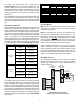
AdditionAl notes
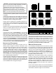
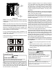
1. There are (3) 7-segment LED displays on the PCB.
Refer to the Troubleshooting chart at the end of this
manual for denitions of the LED status.
2. “TERM” dip switch is used for communications bus
conguration. Leave the settings to the factory default
position.
3. “LEARN” push button is used to reset the communications
between the equipment. Used only for troubleshooting
purposes.
4. Press “TEST” push button, during system “Standby”
mode to turn on both the compressor and outdoor fan
for ve seconds.
5. The “RECALL” push button is used to retrieve the six
most recent faults. The control must be in Standby Mode
(no thermostat inputs) to use the feature. Depress the
push button for approximately two seconds and less
than ve seconds. The 7-segment LED displays will
then display the six most recent faults beginning with
the most recent fault and decrementing to the least
recent fault. The faults may be cleared by depressing
the button for greater than ve seconds. Consecutively
repeated faults are displayed a maximum of three
times. Refer to the fault code denitions at the end of
this manual for more details.
6. A forced defrost can be initiated by pressing “TEST” and
“RECALL” push buttons simultaneously for more than
1 second with a valid call for heat. The forced defrost
can be terminated by
• A 10 minute lapse in time,
• A coil temperature rise above 75°F or
• By pressing the two buttons again for more than 1
second.
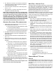
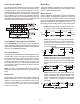
comfortBrIdge™ SyStem
overview
The ComfortBridge based two stage heating and air condi-
tioning system uses an indoor unit and outdoor unit digitally
communicating with one another via a two-way communica-
tions path.
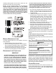
In a traditional system, the thermostat sends commands to
the indoor and outdoor units via analog 24 VAC signals. It is
a one-way communication path in that the indoor and outdoor
units typically do not return information to the thermostat.