
Installation Instructions


6
AUXILIARY ALARM SWITCH
The control is equipped with two Auxiliary Alarm terminals labeled
CAS which can be utilized with communicating mode setups (typi-
cally used for condensate switch wiring but could be used with
compatible C0
2
sensors or fire alarms).
Legacy mode use
In a legacy system (Non-communicating), this feature is not op-
erational. Any auxiliary alarm switch must be used to interrupt
the Y1 signal either to the indoor or outdoor unit.
Communication mode use
This feature can be activated or deactivated through the thermo-
stat user menus. An auxiliary alarm switch must be normally closed
and open when the base pan’s water level in the evaporator coil
reaches a particular level. The control will respond by turning off
the outdoor compressor and display the proper fault codes. If the
switch is detected closed for 30 seconds, normal operation re-
sumes and the error message will be removed.
Air Handler Integrated
Control Module
Typical Single-Stage Cool,
Single-Stage Heat Thermostat
Dehumidistat
[Optional]
Remote Condensing Unit
(Single-Stage AC)
NEU
HOT
12RCG
W1 Y1 Y2
O
DEHUM
RCG
W1 Y1
RC
Y
Place Jumper Between Y1
and O for Proper
Dehumidification Operation
and Proper Ramping
Profile Operation
W2
Figure 8 - Typical Single-Stage Cooling with
Single-Stage Heating
Air Handler Integrated
Control Module
Typical Two-Stage Cool,
Two-Stage Heat Thermostat
Dehumidistat
[Optional]
Remote Condensing Unit
(Two-Stage AC)
NEU
HOT
12RCG
W1 W2 Y1 Y2
O
DEHUM
RCG
W1 W2 Y1 Y2
RC
Y1 Y2
Place Jumper Between Y1
and O for Proper
Dehumidification Operation
and Proper Ramping
Profile Operation
Figure 9 - Typical Two-Stage Cooling with
Two Stage Heating
12RC
A
ir Handler
Integrated Control Module
Typical Single-Stage Cool,
Single-Stage Heat
Heat Pump Thermostat
Dehumidistat
[Optional]
G
W1 W2 Y1 Y2
O
DEHUM
Remote Condensing Unit
(Single-Stage HP)
NEU
HOT
W/E
RCG
Y1
O
RC
W1 Y
O
Figure 10 - Typical Single-Stage Heat Pump with
Auxiliary/Emergency Heating
12RC
A
ir Handler
Integrated Control Module
Typical Two-Stage Cool,
Two-Stage Heat
Heat Pump Thermostat
Dehumidistat
[Optional]
G
W1 W2 Y1 Y2
O
DEHUM
Remote Condensing Unit
(Two-Stage HP)
NEU
HOT
W/E
RCG
W2 Y1 Y2
O
RC
W1 Y1 Y2
O
Figure 11 - Typical Two-Stage Heat Pump Heating
and Auxiliary/Emergency Heating
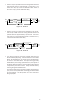
CIRCULATOR BLOWER
CAS
SWITCH
Figure 12 - Auxiliary Alarm Switch
This modular blower is equipped with a variable speed circulator
blower. This blower provides ease in adjusting blower speeds.
The Specification Sheet applicable to your model provides an air-
flow table, showing the relationship between airflow (CFM) and
external static pressure (E.S.P.), for the proper selection of heat-
ing and cooling speeds. The heating blower speed is shipped set
at “21 kW”, and the cooling blower speed is set at “D”. These
blower speeds should be adjusted by the installer to match the
installation requirements so as to provide the correct electric heat-
ing CFM and correct cooling CFM.
Use the CFM LED (green) to obtain an approximate airflow quan-
tity. The green CFM LED blinks once for each 100 CFM of airflow.
1. Determine the tonnage of the cooling system installed with
the modular blower. If the cooling capacity is in BTU/hr
divide it by 12,000 to convert capacity to TONs.
Example: Cooling Capacity of 30,000 BTU/hr.
30,000/12,000 = 2.5 Tons
2. Determine the proper air flow for the cooling system. Most
cooling systems are designed to work with air flows
between 350 and 450 CFM per ton. Most manufacturers
recommend an air flow of about 400 CFM per ton.
Example: 2.5 tons X 400 CFM per ton = 1000 CFM