
Installation Instructions


11
medium, or high continuous fan speed. The low, medium, and
high fan speeds correspond to 25%, 50%, and 75%, respectively,
of the air handlers’ maximum airflow capability. During continu-
ous fan operation, the thermostat sends a fan request along with
the continuous fan demand to the air handler. The air handler, in
turn, sends the demand to the ECM motor. The ECM motor deliv-
ers the requested continuous fan airflow.
CONTROL WIRING
NOTE: Refer to section Electrical Connections for 208/230 volt
line connections to the modular blower.
NOTE: A removable plug connector is provided with the control to
make thermostat wire connections. This plug may be removed,
wire connections made to the plug, and replaced. It is STRONGLY
recommended that you do no connect multiple wires into a single
terminal. Wire nuts are recommended to ensure one wire is used
for each terminal.
Typical 18 AWG thermostat wire may be used to wire the system
components. 150 feet is the maximum recommended length of
wire recommended between indoor and outdoor unit, or between
indoor unit and thermostat.
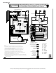
Only data lines 1 and 2 are required between the indoor and out-
door units. The included 40VA, 208/230 VAC to 24 VAC transformer
must be installed in the outdoor unit to provide 24 VAC power to
the outdoor unit’s electronic control. See kit instructions for mount-
ing and wiring instructions.
Figure 22 - System Wiring
COMFORTNET™ SYSTEM ADVANCED FEATURES
The ComfortNet™ system permits access to additional system in-
formation, advanced setup features, and advanced diagnostic/
troubleshooting features. These advanced features are organized
into a menu structure. See the following MODULAR BLOWER AD-
VANCED FEATURES MENUS section for layout of menu shortcuts.
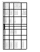
System
System Operating
Mode
Airflow Demand Source
Cooling Air Conditioner
Heating Air Handler
Continuous Fan Thermostat
Cooling Heat Pump
Heat Pump Heating
Only
Heat Pump
HP + Electric Heat
Strips
> of Heat Pump or Air
Handler Demand
Electric Heat Strips
Only
Air Handler
Continuous Fan Thermostat
Air Conditioner +
Air Handler
Heat Pump + Air
Handler
Figure 21 - Airflow Demands
For example, assume the system is a heat pump matched with an
air handler. With a call for low stage cooling, the heat pump will
calculate the system’s low stage cooling airflow demand. The heat
pump will then send a fan request along with the low stage cool-
ing airflow demand to the air handler. Once received, the air han-
dler will send the low stage cooling airflow demand to the ECM
motor. The ECM motor then delivers the low stage cooling air-
flow. See the applicable ComfortNet™ air conditioner or heat pump
installation manual for the airflow delivered during cooling or heat
pump heating.
In continuous fan mode, the CTK0* thermostat provides the air-
flow demand. The thermostat may be configured for a low, me-
dium, or high continuous fan speed. The low, medium, and high
fan speeds correspond to 25%, 50%, and 75%, respectively, of the
air handlers’ maximum airflow capability. During continuous fan
operation, the thermostat sends a fan request along with the con-
tinuous fan demand to the air handler. The air handler, in turn,
sends the demand to the ECM motor. The ECM motor delivers
the requested continuous fan airflow.
1
2
R
C
1
2
R
C
1
2
R
C
CTK04