
Installation Instructions


37
RAMPING PROFILES
The variable-speed circulator offers four different ramping
profiles. These profiles may be used to enhance cooling per-
formance and increaqse comfort level. Select ramping pro-
files on the user menu.
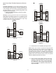
Profile A (1) provides only an OFF delay of one (1) minute
at 100% of the cooling demand airflow.
OFF
100% CFM 100% CFM
1 min
OFF
Figure 58
• Profile B (2) ramps up to full cooling demand airflow
by first stepping up to 50% of the full demand for 30
seconds. The motor then ramps to 100% of the
required airflow. A one (1) minute OFF delay at
100% of the cooling airflow is provided.
50% CFM
1/2 min
100% CFM
100% CFM
1 min
OFF
OFF
Figure 59
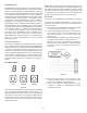
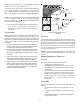
• Profile C (3) ramps up to 85% of the full cooling demand
airflow and operates there for approximately 7 1/2
minutes. The motor then steps up to the full demand
airflow. Profile C also has a one (1) minute 100% OFF
delay.
100% CFM
OFF
OFF
Figure 60
• Profile D (4) ramps up to 50% of the demand for 1/2
minute, then ramps to 85% of the full cooling demand
airflow and operates there for approximately 7 1/2
minutes. The motor then steps up to the full demand
airflow. Profile D has a 1/2 minute at 50% airflow OFF
delay.
OFF
OFF
Figure 61
115 VOLT LINE CONNECTION OR ELECTRONIC AIR CLEANER
T
O
AVOID
PERSONAL
INJURY
OR
DEATH
,
DUE
TO
ELECTRICAL
SHOCK
,
DISCONNECT
ELECTRICAL
POWER
BEFORE
SERVICING
OR
CHANGING
ANY
ELECTRICAL
WIRING
.
WARNING
The accessory load specifications are as follows:
EAC 1.0 AMP maximum at 120 VAC
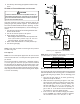
The furnace integrated control module is equipped with a
line voltage accessory terminal for controlling power to an
optional field supplied electronic air cleaner or any device
required to operate inparallel with a circulating fan de-
mand.
To connect an electronic air cleaner using the line voltage
EAC terminal:
• Turn OFF power to the furnace before installing
any accessories.
• Follow the air cleaner manufacturers’ instructions
for locating, mounting, grounding, and controlling
accessories. Utilize 1/4” quick connect terminals
to make accessory wiring connections to the
furnace integrated control module.
• Connect the hot terminal utilized for accessory
operation to the EAC terminal and the neutral side
of power to NEUTRAL bus on the integrated furnace
control or the neutral connection in the furnace
junction box.
• All field wiring must conform to applicable codes.
• If it is necessary for the installer to supply additional
line voltage wiring to the inside of the furnace, the
wiring must conform to all local codes, and have a
minimum temperature rating of 105°C.
• All line voltage wire splices must be made inside
the furnace junction box.
S
TARTUP
P
ROCEDURE
& A
DJUSTMENT
Furnace must have a 115 VAC power supply properly connected
and grounded. Proper polarity must be maintained for correct
operation. In addition to the following start-up and adjust-
ment items, refer to further information in Operational Checks
section.
DRAIN TRAP PRIMING
The drain trap MUST be primed prior to furnace startup. To
prime, fill both sides of the drain trap with water. This
ensures proper furnace drainage upon startup and prohibits
the possibility of flue gases escaping through the drain sys-
tem.
FURNACE OPERATION
Purge gas lines of air prior to startup. Be sure not purge lines
into an enclosed burner compartment. Follow NFPA 54, Na-
tional Fuel Gas Code for proper purging methods. In