
Specifications
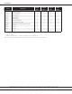
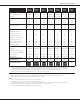
Table Of Contents

Product Specifications
2 www.goodmanmfg.com SS-DSXC16
SS-DSXC16 www.goodmanmfg.com 3
DSXC16
0241AA/B
DSXC16
0241AC
DSXC16
DSXC16
0361AA/B
DSXC16
0361AC
DSXC16
0481B*
DSXC16
0601B*
Nominal Cooling (BTU/h) 24,000 24,000 24,000 36,000 36,000 48,000 60,000
Decibels 71 71 71 70.4/70.9 70.4/70.9 74 75
RLA 10.3 11.7 11.7 16.7 15.3 21.2 28.8
LRA 52.0 58.0 58.3 82.0 83.0 104.0 152.9
Horsepower (RPM) 1/6 1/6 1/6 1/6 1/6 1/6 1/6
FLA 1.1 1.1 1.1 0.9 0.9 1.2 1.0
Refrigerant Line Size¹
Liquid Line Size (“O.D.) ⅜" ⅜" ⅜" ⅜" ⅜" ⅜" ⅜"
Sucon Line Size (“O.D.) ¾" ¾" ¾" ⅞" ⅞" 1⅛" 1⅛"
Refrigerant Connecon Size
Liquid Valve Size (“O.D.) ⅜" ⅜" ⅜" ⅜" ⅜" ⅜" ⅜"
Sucon Valve Size (“O.D.) ¾" ¾" ¾" ¾" ¾" ⅞" ⅞"
Valve Connecon Type Sweat Sweat Sweat Sweat Sweat Sweat Sweat
Refrigerant Charge 97 97 62 107 107 124 197
Voltage-Hz 208/230-60 208/230-60 208/230-60 208/230-60 208/230-60 208/230-60 208/230-60
Minimum Circuit Ampacity ² 14.0 15.7 15.7 21.8 20.0 27.7 37.2
Max. Overcurrent Protecon ³ 20 20 25 35 35 45 60
Min / Max Volts 197/253 197/253 197/253 197/253 197/253 197/253 197/253
Power Supply ½" or ¾" ½" or ¾" ½" or ¾" ½" or ¾" ½" or ¾" ½" or ¾" ½" or ¾"
181 181 181 184 184 219 279
198 198 198 202 202 241 301
ENERGY STAR®
NO
• Proper sizing and installaon of equipment is crical to achieving opmal performance. Split system air condioners and heat pumps must
be matched with appropriate coil components to meet ENERGY STAR criteria. Ask your contractor for details or visit www.energystar.gov.
• The www.energystar.gov website provides up-to-date system combinaons cered to meet ENERGY STAR requirements.
See Pages 24-25 for all ENERGY STAR cered combinaons as of this document’s revision date.
¹ Tested and rated in accordance with AHRI Standard 210/240
² Wire size should be determined in accordance with Naonal Electrical Codes; extensive wire runs will require larger wire sizes
³ Must use me-delay fuses or HACR-type circuit breakers of the same size as noted.
• Always check the S&R plate for electrical data on the unit being installed.
• Installer will need to supply ⅞” to 1⅛” adapters for sucon line connecons.
• Unit is charged with refrigerant for 15’ of ⅜” liquid line. System charge must be adjusted per Installaon Instrucons Final Charge Procedure.
• Installaon of these units requires the specied TXV Kit to be installed on the indoor coil. THE SPECI-
FIED TXV IS DETERMINED BY THE OUTDOOR UNIT, NOT THE INDOOR COIL.