
Installation Manual

4
R
EFRIGERANT
L
INE
C
ONNECTIONS
IMPORTANT
To avoid overheating the service valve, TXV valve, or filter drier
while brazing, wrap the component with a wet rag, or use a
thermal heat trap compound. Be sure to follow the
manufacturer’s instruction when using the heat trap compound.
Note: Remove Schrader valves from service valves before brazing
tubes to the valves. Use a brazing alloy of 2% minimum silver
content. Do not use flux.
Torch heat required to braze tubes of various sizes is
proportional to the size of the tube. Tubes of smaller size require
less heat to bring the tube to brazing temperature before adding
brazing alloy. Applying too much heat to any tube can melt the
tube. Service personnel must use the appropriate heat level
for the size of the tube being brazed. NOTE: The use of a heat
shield when brazing is recommended to avoid burning the serial
plate or the finish on the unit.
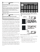
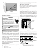
1. The ends of the refrigerant lines must be cut square,
deburred, cleaned, and be round and free from nicks or
dents. Any other condition increases the chance of a
refrigerant leak.
2. “Sweep” the refrigerant line with nitrogen or inert gas
during brazing to prevent the formation of copper-oxide
inside the refrigerant lines. The POE oils used in R-410A
applications will clean any copper-oxide present from the
inside of the refrigerant lines and spread it throughout
the system. This may cause a blockage or failure of the
metering device.
3. After brazing, quench the joints with water or a wet cloth
to prevent overheating of the service valve.
4. Ensure the filter drier paint finish is intact after brazing. If
the paint of the steel filter drier has been burned or
chipped, repaint or treat with a rust preventative. This is
especially important on suction line filter driers which are
continually wet when the unit is operating.
NOTE: Be careful not to kink or dent refrigerant lines. Kinked or
dented lines will cause poor performance or compressor damage.
Do NOT make final refrigerant line connection until plugs are
removed from refrigerant tubing.
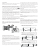
NOTE: Before brazing, verify indoor piston size by checking the
piston kit chart packaged with indoor unit.
L
EAK
T
ESTING
(N
ITROGEN
OR
N
ITROGEN
-T
RACED
)
T
O
AVOID
THE
RISK
OF
FIRE
OR
EXPLOSION
,
NEVER
USE
OXYGEN
,
HIGH
PRESSURE
AIR
OR
FLAMMABLE
GASES
FOR
LEAK
TESTING
OF
A
REFRIGERATION
SYSTEM
.
WARNING
T
O
AVOID
POSSIBLE
EXPLOSION
,
THE
LINE
FROM
THE
NITROGEN
CYLINDER
MUST
INCLUDE
A
PRESSURE
REGULATOR
AND
A
PRESSURE
RELIEF
VALVE
. T
HE
PRESSURE
RELIEF
VALVE
MUST
BE
SET
TO
OPEN
AT
NO
MORE
THAN
150
PSIG
.
WARNING
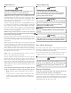
Pressure test the system using dry nitrogen and soapy water to
locate leaks. If you wish to use a leak detector, charge the sys-
tem to 10 psi using the appropriate refrigerant then use nitro-
gen to finish charging the system to working pressure then ap-
ply the detector to suspect areas. If leaks are found, repair them.
After repair, repeat the pressure test. If no leaks exist, proceed to
system evacuation.
S
YSTEM
E
VACUATION
Condensing unit liquid and suction valves are closed to contain
the charge within the unit. The unit is shipped with the valve
stems closed and caps installed. Do not open valves until the
system is evacuated.
REFRIGERANT UNDER PRESSURE!
F
AILURE
TO
FOLLOW
PROPER
PROCEDURES
MAY
CAUSE
PROPERTY
DAMAGE
,
PERSONAL
INJURY
OR
DEATH
.
WARNING
NOTE: Scroll compressors should never be used to evacuate or
pump down a heat pump or air conditioning system.
P
ROLONGED
OPERATION
AT
SUCTION
PRESSURES
LESS
THAN
20
PSIG
FOR
MORE
THAN
5
SECONDS
WILL
RESULT
IN
OVERHEATING
OF
THE
SCROLLS
AND
PERMANENT
DAMAGE
TO
THE
SCROLL
TIPS
,
DRIVE
BEARINGS
AND
INTERNAL
SEAL
.
CAUTION
1. Connect the vacuum pump with 250 micron capability to
the service valves.
2. Evacuate the system to 250 microns or less using suction
and liquid service valves. Using both valves is necessary
as some compressors create a mechanical seal separating
the sides of the system.
3. Close pump valve and hold vacuum for 10 minutes.
Typically pressure will rise during this period.
• If the pressure rises to 1000 microns or less and remains
steady the system is considered leak-free; proceed to
startup.
• If pressure rises above 1000 microns but holds steady
below 2000 microns, moisture and/or noncondensibles
may be present or the system may have a small leak.
Return to step 2: If the same result is encountered check
for leaks as previously indicated and repair as necessary
then repeat evacuation.
• If pressure rises above 2000 microns, a leak is present.
Check for leaks as previously indicated and repair as
necessary then repeat evacuation.