
Specifications

4 www.goodmanmfg.com SS-GCVC96
SS-GCVC96 www.goodmanmfg.com 5
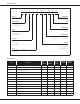
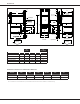
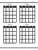
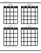
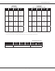
Dimensions
A
34½
4⅛
11⅜
14¾
25⅛
28¾
C
6⅞ 6⅞
11⅜
14⅞
14¾
25⅛
3½
2½
2
1⅞
2⅝
23
14
1⅜
1½
1⅝
E
D
Unfolded Flanges
18⅛
Unfolded Flanges
20⅛
Folded Flanges
2⅝
1⅞
2½
6½
2
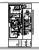
Front View
Right-Side View
Low-Voltage
Electrical Outlet
Alternate Gas
High-Voltage
Electrical Outlet
Standard Drain Trap
Drain Trap Holes
Alternate
Gas Supply
Alternate Vent/
High-Voltage
Electrical Outlet
Right Side Exterior
Drain Trap Holes
Low-Voltage
Electrical Outlet
Air
Discharge
Air
Discharge
Folded Flanges
B
18¼
Air
Return
Air
Discharge
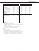
Model A B C D E
GCVC960403BNA 17½" 14⅝" 14" 14½" 16"
GCVC960603BNA 17½" 14⅝" 14" 14½" 16"
GCVC960804CNA 21" 18⅛" 17½" 18" 19½"
GCVC961005CNA 21" 18⅛" 17½" 18" 19½"
GCVC961205DNA 24½” 21⅝" 21" 21½" 23"
Minimum Clearances to Combustible Materials
Position Sides Rear Front Bottom Flue Top
Downow 0" 0" 3" NC 0" 1"
Horizontal 6" 0" 3" C 0" 6"
C = If placed on combusble oor, the oor MUST be wood ONLY.
NC = For installaon on non-combusble oors only. A combusble oor sub-base must be used for installaons on combusble ooring.