
Instructions / Assembly


9
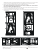
The return ductwork is to be connected to the air handler bottom (upflow configuration).
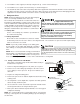
10 Return Air Filters
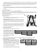
Each installation must include a return air filter. This filtering may be performed at the air handler using the factory filter rails
or externally such as a return air filter grille. When using the factory filter rails, a nominal 16x20x1”, 20x20x1” or 24x20x1”
(actual dimension must be less than 23-½”x20”) filter can be installed on a B, C and D cabinet respectively (the cabinet size
is the seventh letter of the model number).
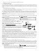
11 Electric Heat
Refer to the installation manual provided with the electric heat kit for the correct installation procedure. All electric heat must
be field installed. If installing this option, the ONLY heat kits that are permitted to be used are the HKS series. Refer to the
air handler unit’s Serial and Rating plate or the HKS specification sheets to determine the heat kits compatible with a given
air handler. No other accessory heat kit besides the HKS series may be installed in these air handlers.
The heating mode temperature rise is dependent upon the system airflow, the supply voltage, and the heat kit size (kW)
selected. Use data provided in Tables 3, 4 and 5 to determine the temperature rise (°F).
NOTE: For installations not indicated above the following formula is to be used:
TR = (kW x 3412) x (Voltage Correction) / (1.08 x CFM)
Where: TR = Temperature Rise
kW = Heater Kit Actual kW
3412 = Btu per kW
VC* = .96 (230 Supply Volts)
= .92 (220 Supply Volts)
= .87 (208 Supply Volts)
1.08 = Constant
CFM = Measured Airflow
VC* (Voltage Correction)
NOTE: The Temperature Rise Tables can also be used to estimate the air handler airflow delivery. When using these tables
for this purpose set the room thermostat to maximum heat and allow the system to reach steady state conditions. Insert two
thermometers, one in the return air and one in the supply air. The temperature rise is the supply air temperature minus the
return air temperature. Using the temperature rise calculated, CFM can be estimated from the TR formula above. See
Technical Manual and/or Service Manual for more information.
3 5 6 8 10 15 19 20 21 or 25
AVPTC24B14
550 650 700 800 850 NR NR NR NR
AVPTC30B14
600 700 750 875 950 NR NR NR NR
AVPTC36C14
NR 850 900 1000 1200 1440 1500 1500 NR
AVPTC48C14
NR 850 900 1000 1200 1440 1500 1500 NR
AVPTC42D14
†
850** 1250 1300 1500 1550 1720 NR 1800 NR
AVPTC48D14
††
NR 1250 1300 1500 1550 1720 NR 1815 1850
AVPTC60D14
†††
NR 1250 1300 1500 1550 1780 NR 1850 1850
MINIMUM CFM REQUIRED FOR HEATER KITS
Heater Kit (Kw)
Please refer to page 16 for specific heater kit application guidelines.
Table 6
3568101519/2025
800 1118223035
1000 9 1418242842
1200 7 12152024354759
1400 6 10131720304051
1600 6 9 11 15 18 27 35 44
1800 5 8 10 13 16 24 31 39
2000 4 7 9 1214212835
CFM
HEAT KIT NOMINAL kW
220/1/60 SUPPLY VOLTAGE - TEMP. RISE °F
Table 4
3568101519/2025
800 12 19 23 31 37
1000 9 15 19 25 30 44
1200 8 12 15 21 25 37 49 62
1400 7 11 13 18 21 32 42 53
1600 6 9 12 15 19 28 37 46
1800 5 8 10 14 16 25 33 41
2000 5 7 9 12 15 22 30 37
CFM
HEAT KIT NOMINAL kW
230/1/60 SUPPLY VOLTAGE - TEMP. RISE °F
Table 3
3 5 6 8 10 15 19/20 25
800 10 17 21 28 33
1000 8 13 17 22 27 40
1200 7 11141922334556
1400 6 10121619293848
1600 5 8 10 14 17 25 33 42
1800 5 7 9 12 15 22 30 37
2000 4 7 8 11 13 20 27 33
CFM
HEAT KIT NOMINAL kW
208/1/60 SUPPLY VOLTAGE - TEMP. RISE °F
Table 5