
Installation Instructions


10
Corrections must be in accordance with the latest edition of
the National Fuel Gas Code NFPA 54/ANSI Z223.1 and/or CAN/
CSA B149 Installation Codes.
If resizing is required on any portion of the venting system, use
the appropriate table in the latest edition of the National Fuel
Gas Code ANSI Z223.1.
THERMOSTAT L OCATION
In an area having good air circulation, locate the thermostat
about five feet high on a vibration-free inside wall. Do not install
the thermostat where it may be influenced by any of the follow-
ing:
• Drafts, or dead spots behind doors, in corners, or under
cabinets.
• Hot or cold air from registers.
• Radiant heat from the sun.
• Light fixtures or other appliances.
• Radiant heat from a fireplace.
• Concealed hot or cold water pipes, or chimneys.
• Unconditioned areas behind the thermostat, such as
an outside wall.
Consult the instructions packaged with the thermostat for mount-
ing instructions and further precautions.
C
OMBUSTION
AND
V
ENTILATION
A
IR
R
EQUIREMENTS
T
O
AVOID
PROPERTY
DAMAGE
,
PERSONAL
INJURY
OR
DEATH
,
SUFFICIENT
FRESH
AIR
FOR
PROPER
COMBUSTION
AND
VENTILATION
OF
FLUE
GASES
MUST
BE
SUPPLIED
. M
OST
HOMES
REQUIRE
OUTSIDE
AIR
BE
SUPPLIED
INTO
THE
FURNACE
AREA
.
WARNING
Improved construction and additional insulation in buildings have
reduced heat loss by reducing air infiltration and escape around
doors and windows. These changes have helped in reducing
heating/cooling costs but have created a problem supplying
combustion and ventilation air for gas fired and other fuel burn-
ing appliances. Appliances that pull air out of the house (clothes
dryers, exhaust fans, fireplaces, etc.) increase the problem by
starving appliances for air.
House depressurization can cause back drafting or improper
combustion of gas-fired appliances, thereby exposing building
occupants to gas combustion products that could include car-
bon monoxide.
If this furnace is to be installed in the same space with other
gas appliances, such as a water heater, ensure there is an
adequate supply of combustion and ventilation air for all appli-
ances. Refer to the latest edition of the National Fuel Gas
Code NFPA 54/ANSI Z223.1 or CAN/CSA B149 Installation
Codes or applicable provisions of the local building codes for
determining the combustion air requirements for the appliances.
This furnace must use indoor air for combustion. It cannot be
installed as a direct vent (i.e., sealed combustion) furnace.
Most homes will require outside air be supplied to the furnace
area by means of ventilation grilles or ducts connecting directly
to the outdoors or spaces open to the outdoors such as attics
or crawl spaces.
CATEGORY I VENTING (VERTICAL VENTING)
T
O
PREVENT
POSSIBLE
PERSONAL
INJURY
OR
DEATH
DUE
TO
ASPHYXIATION
,
THIS
FURNACE
MUST
BE
C
ATEGORY
I
VENTED
. D
O
NOT
VENT
USING
C
ATEGORY
III
VENTING
.
WARNING
Category I Venting is venting at a non-positive pressure. A
furnace vented as Category I is considered a fan-assisted ap-
pliance and the vent system does not have to be “gas tight.”
NOTE: Single stage gas furnaces with induced draft blowers
draw products of combustion through a heat exchanger allow-
ing, in some instances, common venting with natural draft ap-
pliances (i.e. water heaters). All installations must be vented in
accordance with National Fuel Gas Code NFPA 54/ANSI Z223.1
- latest edition.
NOTE: The vertical height of the Category I venting system
must be at least as great as the horizontal length of the venting
system.
T
O
PREVENT
POSSIBLE
PERSONAL
INJURY
OR
DEATH
DUE
TO
ASPHYXIATION
,
COMMON
VENTING
WITH
OTHER
MANUFACTURER
’
S
INDUCED
DRAFT
APPLIANCES
IS
NOT
ALLOWED
.
WARNING
The minimum vent diameter for the Category I venting system
is as shown:
UPFLOW COUNTERFLOW
060 4 inch 4 inch
080 4 inch 4 inch
100 5 inch 4 inch
MINIMUM VENT
MODEL
Under some conditions, larger vents than those shown above
may be required or allowed. When an existing furnace is re-
moved from a venting system serving other appliances, the
venting system may be too large to properly vent the remaining
attached appliances.
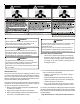
Furnaces are shipped with the induced draft blower discharg-
ing from the top of the furnace. (“Top” is as viewed for an upflow
installation.) The induced draft blower on *MVC8 models can
be rotated 90 degrees for Category I venting. For furnaces
installed vertically or horizontally, a four-inch single wall pipe
can be used to extend the induced draft blower outlet 1/2” be-
yond the furnace cabinet. On *MVC8 furnaces installed upflow
or horizontally with left side down, the draft inducer may be
rotated to discharge from the right side of the cabinet. When
rotating the inducer a chimney transition bottom kit (part #
0270F01119) is needed for proper alignment of the inducer out-
let and the vent exit hole in the side of the cabinet. The inducer
may NOT be rotated on *CVC8 model furnaces regardless of
installation position.