
Instructions / Assembly


42
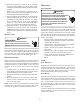
COMFORTNET™ COMPATIBLE FURNACE WITH NON-COMFORTNET
COMPATIBLE
SINGLE-STAGE AIR CONDITIONER
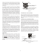
Four wires are required between the furnace and thermostat.
Two wires are required between the furnace control and single
stage air conditioner. For this system configuration, the “Y1”
terminal on the integrated furnace control becomes an output
rather than an input. The “Y1” connection to the outdoor unit is
made using both 4-position thermostat connectors in the CTK0*
kit. Remove the red keying tabs from the on-board connector
block and position both 4-position connector such that “1”, “2”,
“R”, “C”, and “Y1” positions are filled.
NOTE: The cooling CFM for this installation must be set up at
the communicating thermostat through ComfortNet >furnace
menu > non com menu.
12RC
C Y
ComfortNet Compatible
Furnace Integrated
Control Module
CTK0*
Thermostat
Non- Compatible
Single Stage AC
ComfortNet
G
W1 W2 Y1 Y2
O
12RC
4-Position Connectors
from CTK0*
Thermostat Kit
System Wiring between Furnace and Non-Communicating Compatible
Single Stage Air Conditioner
Figure 56
COMFORTNET SYSTEM ADVANCED FEATURES
The ComfortNet system permits access to additional system in-
formation, advanced setup features, and advanced diagnostic/
troubleshooting features. These advanced features are orga-
nized into a menu structure. The menus are accessed and navi-
gated by means of the CTK0* thermostat. For details, see
the thermostat instruction manual.
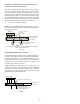
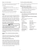
PCBKF105 IFC has the added feature of 24 VAC input to G
terminal when using a communicating thermostat. ERV/HRV
and other accessories can send a signal to the G terminal
and energize the continuous fan. The continuous fan speed
ComfortNet System Advanced Features
W1 W2 Y1 Y2 O DEHUM
24 vac "G" input to Furnace
Integrated Control module From
ERV / HRV or Similar Devices
1
1
2RC
2
Furnace Integrated
Control Module
RC
G
CTK0* Thermostat
4-Pin (X2), 7 Pin, or 9 Pin Connecto
r
Diagram 1