
Instructions / Assembly


41
demand and transmits the demand along with a fan request
to the indoor unit. The indoor unit then sends the demand
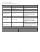
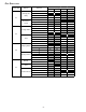
to the ECM motor. The table below lists the various
ComfortNet systems, the operating mode, and airflow de-
mand source.
For example, assume the system is an air conditioner
matched with a furnace. With a call for low stage cooling,
the air conditioner will calculate the system’s low stage cool-
ing airflow demand. The air conditioner will then send a
fan request along with the low stage cooling airflow de-
mand to the furnace. Once received, the furnace will send
the low stage cooling airflow demand to the ECM motor.
The ECM motor then delivers the low stage cooling airflow.
See the applicable ComfortNet air conditioner or heat pump
installation manual for the airflow delivered during cooling
or heat pump heating.
In continuous fan mode, the CTK0* thermostat provides the
airflow demand. The thermostat may be configured for a
low, medium, or high continuous fan speed. The low, me-
dium, and high fan speeds correspond to 25%, 50%, and
75%, respectively, of the furnaces’ maximum airflow capa-
bility. During continuous fan operation, the thermostat
sends a fan request along with the continuous fan demand
to the furnace. The furnace, in turn, sends the demand to
the ECM motor. The ECM motor delivers the requested con-
tinuous fan airflow.
FOSSIL FUEL APPLICATIONS
This furnace can be used in conjunction with a ComfortNet
compatible heat pump in a fossil fuel application. A fossil
fuel application refers to a combined gas furnace and heat
pump installation which uses an outdoor temperature sensor
to determine the most cost efficient means of heating (heat
pump or gas furnace). The balance point temperature may
be adjusted via the CTK0* thermostat advanced user menus
(see CTK0* instructions for additional information).
CTK0* WIRING
NOTE: A removable plug connector is provided with the
control to make thermostat wire connections. This plug may
be removed, wire connections made to the plug, and replaced.
It is STRONGLY recommended that you do not connect
multiple wires into a single terminal. Wire nuts are
recommended to ensure one 18 AWG wire is used for each
terminal. Failure to do so may result in intermittent
operation.
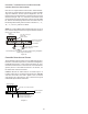
12RC
12
RC
CTK0*
Thermostat
ComfortNet Compatible Furnace
Integrated Control Module
ComfortNet Compatible AC/HP
Integrated Control Module
12
R
C
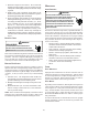
System Wiring using Four-Wires
Figure 54
FOUR-WIRE INDOOR AND OUTDOOR WIRING
Typical ComfortNet wiring will consist of four wires between
the indoor unit and outdoor unit and between the indoor unit
and thermostat. The required wires are: (a) data lines, 1
and 2; (b) thermostat “R” (24 VAC hot) and “C” (24 VAC
common).
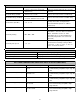
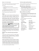
TWO-WIRE OUTDOOR, FOUR-WIRE INDOOR WIRING
Two wires can be utilized between the indoor and outdoor units.
For this wiring scheme, only the data lines, 1 and 2, are needed
between the indoor and outdoor units. A 40VA, 208/230 VAC to
24VAC transformer must be installed in the outdoor unit to pro-
vide 24VAC power to the outdoor unit’s electronic control. See
instruction manual provided with the thermostat for wiring
instructions.
NOTE: Use of a transformer is recommended if installing a
dual fuel/fossil fuel system with a CTK01* or CTK02*. Fail-
ure to use the transformer in the outdoor unit could result in
over loading of the furnace transformer. Follow the thermo-
stat manufacturers recommendation on when an outdoor
transformer is needed. Do not attempt to install an outdoor
transformer when using an inverter type unit.
12RC
12RC
CTK0*
Thermostat
ComfortNet Compatible
Furnace Integrated
Control Module
ComfortNet Compatible
AC/HP Integrated
Control Module
40VA Transformer
208/230 VAC
24 VAC
12RC
System Wiring using Two-Wires between Furnace and AC/HP and Four-Wires
Between Furnace and Thermostat
Figure 55