
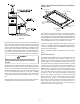
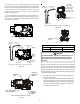
Instructions / Assembly

40
In general lower heating speeds will: reduce electrical consump-
tion, lower operating sound levels of the blower, and increase the
outlet air temperature delivered to the home. The speeds avail-
able allow the blower performance to be optimized for the par-
ticular homeowner’s needs.
Continuous fan speeds that provide 25, 50, 75 and 100% of
the furnace’s maximum airflow capability are selectable via
dip switches S5- 3, 4.
Example: If the furnace’s maximum airflow capability
is 2000 CFM and 25% continuous fan speed
is selected, the continuous fan speed will
be 0.25 x 2000 CFM = 500 CFM.
12
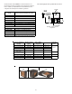
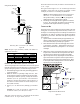
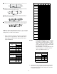
90 seconds OFF OFF
120 seconds ON OFF
150 seconds* OFF ON
180 seconds ON ON
Heat Off Delay Dip Switches
(*Indicates factory setting)
Heat OFF Delay
DIP Sw itch No.
Sw itch Bank: S1
BLOWER HEAT OFF DELAY TIMINGS
The integrated control module provides a selectable heat off
delay function. The heat off delay period may be set to 90, 120,
150, 180 seconds using the DIP switches or jumper provided on
the control module. The delay is factory shipped at 150 seconds
but may be changed to suit the installation requirements and/or
homeowner preference. Refer to the following figures for switch
positions and corresponding delay times.
C
OMFORT
N
ET
™ S
YSTEM
OVERVIEW
The ComfortNet system is a system that includes a ComfortNet
compatible furnace and air conditioner or heat pump with a CTK0*
thermostat. A valid ComfortNet system could also be a compat-
ible furnace, CTK0* thermostat and non-compatible, single stage
air conditioner. Any other system configurations are considered
invalid ComfortNet systems and must be connected as a tradi-
tional (or non-communicating) system (see Electrical Connec-
tions for wiring connections).
A ComfortNet heating/air conditioning system differs from a
non-communicating/traditional system in the manner in which
the indoor unit, outdoor unit and thermostat interact with one
another. In a traditional system, the thermostat sends com-
mands to the indoor and outdoor units via analog 24 VAC signals.
It is a one-way communication path in that the indoor and out-
door units typically do not return information to the thermostat.
In a ComfortNet system, the indoor unit, outdoor unit, and
thermostat comprising a ComfortNet system “communicate” digi-
tally with one another, creating a two-way communications path.
The thermostat still sends commands to the indoor and outdoor
units. However, the thermostat may also request and receive
information from both the indoor and outdoor units. This infor-
mation may be displayed on the ComfortNet thermostat. The
indoor and outdoor units also interact with one another. The
outdoor unit may send commands to or request information from
the indoor unit. This two-way digital communications between
the thermostat and subsystems (indoor/outdoor unit) and be-
tween subsystems is the key to unlocking the benefits and fea-
tures of the ComfortNet system.
Two-way digital communications is accomplished using only two
wires. The thermostat and subsystem controls are power with
24 VAC. Thus, a maximum of 4 wires between the equipment
and thermostat is all that is required to operate the system.
PCBKF105 IFC has the added feature of 24 VAC input to G
terminal when using a communicating thermostat (CTK0*).
ERV/HRV and other accessories can send a 24 VAC signal to
the G terminal and energize the continuous fan. The con-
tinuous fan speed can be adjusted on switch bank S5, DIP
switch 3 & 4.
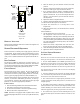
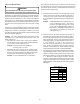
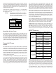
AIRFLOW CONSIDERATION
System
System
Operating Mode
Airflow Demand
Source
Cooling Air Conditioner
Heating Furnace
Continuous Fan Thermostat
Cooling Heat Pump
Heat Pump Heating
Only
Heat Pump
Auxiliary Heating Furnace
Continuous Fan Thermostat
Cooling Furnace
Heating Furnace
Continuous Fan Thermostat
Furnace + Non-
Comm 1s tg Air
Conditioner
Air Conditioner +
Furnace
Heat Pump +
Furnace
Airflow demands are managed differently in a fully commu-
nicating system than they are in a non-communicating wired
system. The system operating mode (as determined by the
thermostat) determines which unit calculates the system air-
flow demand. If the indoor unit is responsible for determin-
ing the airflow demand, it calculates the demand and sends
it to the ECM motor. If the outdoor unit or thermostat is
responsible for determining the demand, it calculates the