
Instructions / Assembly


12
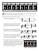
CAS
SWITCH
Figure 19
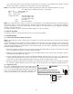
ON
OFF
Move to the
ON position
to enable
dehumidification
S5 S6 S7 S8
Dip Switches -
Dehumidification Enable
Figure 18
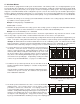
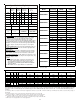
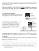
To install/connect a dehumidistat:
1. Turn OFF power to air handler.
2. Secure the dehumidistat neutral wire (typically the white lead) to the screw terminal marked “DEHUM” on the air
handler’s integrated control module.
3. Secure the dehumidistat hot wire (typically the black lead) to the screw terminal
marked “R” on the air handler’s integrated control module.
4. Secure the dehumidistat ground wire (typically the green lead) to the ground
screw on the air handler. NOTE: Ground wire may not be present on all dehumi-
distats.
5. To enable the dehumidification function, move the dehumidification dip switch
(S7) from OFF to ON. See following figure.
6. Turn ON power to air handler.
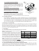
15 Auxiliary Alarm Switch
The control is equipped with two Auxiliary Alarm terminals labeled CAS which can
be utilized with communicating mode setups (typically used for condensate switch
wiring but could be used with compatible C0
2
sensors or fire alarms).
Legacy mode use
In a legacy system (Non-communicating), this feature is not operational. Any auxil-
iary alarm switch must be used to interrupt the Y1 signal either to the indoor or
outdoor unit.
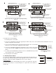
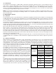
Air Handler Integrated
Control Module
Typical Single-Stage Cool,
Single-Stage Heat Thermostat
Dehumidistat
[Optional]
Remote Condensing Unit
(Single-Stage AC)
NEU
HOT
12RCG
W1 Y1 Y2
O
DEHUM
RCG
W1 Y1
RC
Y
Place Jumper Between Y1
and O for Proper
Dehumidification Operation
and Proper Ramping
Profile Operation
W2
Typical Single-Stage Cooling with Single-Stage Heating
Figure 14
Air Handler Integrated
Control Module
Typical Two-Stage Cool,
Two-Stage Heat Thermostat
Dehumidistat
[Optional]
Remote Condensing Unit
(Two-Stage AC)
NEU
HOT
12RCG
W1 W2 Y1 Y2
O
DEHUM
RCG
W1 W2 Y1 Y2
RC
Y1 Y2
Place Jumper Between Y1
and O for Proper
Dehumidification Operation
and Proper Ramping
Profile Operation
Typical Two-Stage Cooling with Two-Stage Heating
Figure 15
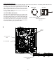
12RC
A
ir Handler
Integrated Control Module
Typical Single-Stage Cool,
Single-Stage Heat
Heat Pump Thermostat
Dehumidistat
[Optional]
G
W1 W2 Y1 Y2
O
DEHUM
Remote Condensing Unit
(Single-Stage HP)
NEU
HOT
W/E
RCG
Y1
O
RC
W1 Y
O
Typical Single-Stage Heat Pump
with Auxiliary/Emergency Heating
Figure 16
12RC
A
ir Handler
Integrated Control Module
Typical Two-Stage Cool,
Two-Stage Heat
Heat Pump Thermostat
Dehumidistat
[Optional]
G
W1 W2 Y1 Y2
O
DEHUM
Remote Condensing Unit
(Two-Stage HP)
NEU
HOT
W/E
RCG
W2 Y1 Y2
O
RC
W1 Y1 Y2
O
Typical Two Stage Heat Pump Heating
and Auxiliary/Emergency Heating
Figure 17