
Condensing Unit & Heat Pump R410A Service Manual

89
SERVICING
S-10 MBR/AR*F ELECTRONIC BLOWER TIME DELAY
RELAY
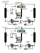
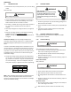
The MBR/AR*F contains an Electronic Blower Time Delay Relay
board, B1370735. This board provides on/o me delays for the
blower motor in cooling and heat pump heang demands when
“G” is energized.
During a cooling or heat pump heang demand, 24Vac is
supplied to terminal “G” of the EBTDR to turn on the blower
motor. The EBTDR iniates a 7 second delay on and then
energizes it’s onboard relay. The relay on the EBTDR board
closes it’s normally open contacts and supplies power to the
blower motor. When the “G” input is removed, the EBTDR
iniates a 65 second delay o. When the 65 seconds delay
expires the onboard relay is de-energized and it’s contacts open
and remove power from the blower motor.
During an electric heat only demand, “W1” is energized but “G”
is not. The blower motor is connected to the normally closed
contacts of the relay on the EBTDR board. The other side of this
set of contacts is connected to the heat sequencer on the heater
assembly that provides power to the rst heater element. When
“W1” is energized, the sequencer will close it’s contacts within
10 to 20 seconds to supply power to the rst heater element
and to the blower motor through the normally closed contacts
on the relay on the EBTDR. When the “W1” demand is removed,
the sequencer opens it contacts within 30 to 70 seconds and
removes power from the heater element and the blower motor.
The EBTDR also contains a speedup terminal to reduce the
delays during troubleshoong of the unit. When this terminal is
shorted to the common terminal, “C”, on the EBTDR board, the
delay ON me is reduced to 3 seconds and the delay OFF me is
reduced to 5 second.
Two addional terminals, M1 and M2, are on the EBTDR board.
These terminals are used to connect the unused leads from the
blower motor and have no aect on the board’s operaon.
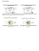
S-11 CHECKING LOSS OF CHARGE PROTECTOR
(Heat Pump Models)
The loss of charge protectors senses the pressure in the liquid
line and will open its contacts on a drop in pressure. the low
pressure control will automacally reset itself with a rise in
pressure.
The low pressure control is designed to cut-out (open) at
approximately 21 PSIG. It will automacally cut-in (close) at
approximately 50 PSIG.Test for connuity using a VOM and if not
as above, replace the control.
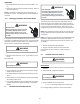
S-12 CHECKING HIGH PRESSURE CONTROL
WARNING
HIGH VOLTAGE!
Disconnect ALL power before servicing
or installing. Multiple power sources
may be present. Failure to do so may
cause property damage, personal injury
or death.
The high pressure control capillary senses the pressure in the
compressor discharge line. If abnormally high condensing
pressures develop, the contacts of the control open, breaking
the control circuit before the compressor motor overloads. This
control is automacally reset.
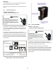
1. Using an ohmmeter, check across terminals of high pressure
control, with wire removed. If not connuous, the contacts
are open.
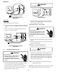
2. Aach a gauge to the dill valve port on the base valve.
With power ON:
Line Voltage now present.
WARNING
3. Start the system and place a piece of cardboard in front of
the condenser coil, raising the condensing pressure.
4. Check pressure at which the high pressure control cuts-out.
If it cuts-out at 610 PSIG ± 10 PSIG, it is operang normally
(See causes for high head pressure in Service Problem Anal-
ysis Guide). If it cuts out below this pressure range, replace
the control.
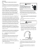
S-13 CHECKING LOW PRESSURE CONTROL
The low pressure control senses the pressure in the sucon
line and will open its contacts on a drop in pressure. The low
pressure control will automacally reset itself with a rise in
pressure.
The low pressure control is designed to cut-out (open) at
approximately 21 PSIG for heat pumps and 55 PSIG for air
condioners.