
Condensing Unit & Heat Pump R410A Service Manual

86
SERVICING
S-1 CHECKING VOLTAGE
1. Remove outer case, control panel cover, etc., from unit being
tested.
With power ON:
Line Voltage now present.
WARNING
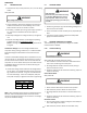
2. Using a voltmeter, measure the voltage across terminals L1
and L2 of the contactor for the condensing unit or at the
eld connecons for the air handler or heaters.
3. No reading - indicates open wiring, open fuse(s) no power or
etc., from unit to fused disconnect service. Repair as
needed.
4. With ample voltage at line voltage connectors, energize the
unit.
5. Measure the voltage with the unit starng and operang,
and determine the unit Locked Rotor Voltage.
NOTE: If checking heaters, be sure all heang elements are
energized.
Locked Rotor Voltage is the actual voltage available at the
compressor during starng, locked rotor, or a stalled condion.
Measured voltage should be above minimum listed in chart
below.
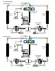
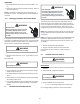
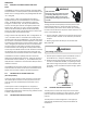
To measure Locked Rotor Voltage aach a voltmeter to the run
"R" and common "C" terminals of the compressor, or to the T1
and T2 terminals of the contactor. Start the unit and allow the
compressor to run for several seconds, then shut down the unit.
Immediately aempt to restart the unit while measuring the
Locked Rotor Voltage.
6. Locked rotor voltage should read within the voltage tabula-
on as shown. If the voltage falls below the minimum volt-
age, check the line wire size. Long runs of undersized wire
can cause low voltage. If wire size is adequate, nofy the
local power company in regard to either low or high voltage.
Unit Supply Voltage
Voltage
Min. Max
208/230
197 253
460 414 506
NOTE: When operang electric heaters on voltages other than
240 volts, refer to the System Operaon secon on electric
heaters to calculate temperature rise and air ow. Low voltage
may cause insucient heang.
S-2 CHECKING WIRING
WARNING
HIGH VOLTAGE!
Disconnect ALL power before servicing
or installing. Multiple power sources
may be present. Failure to do so may
cause property damage, personal injury
or death.
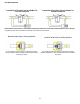
1. Check wiring visually for signs of overheang, damaged insu-
laon and loose connecons.
2. Use an ohmmeter to check connuity of any suspected open
wires.
3. If any wires must be replaced, replace with comparable
gauge and insulaon thickness.
S-3 CHECKING THERMOSTAT and WIRING
Thermostat Wiring: The maximum wire length for 18 AWG
thermostat wire is 100 feet.
S-3A Thermostat Wiring
Line Voltage now present.
WARNING
With power ON, thermostat calling for cooling
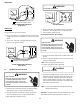
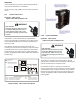
1. Use a voltmeter to check for 24 volts at thermostat wires C
and Y in the condensing unit control panel.
2. No voltage indicates trouble in the thermostat, wiring or
external transformer source.
3. Check the connuity of the thermostat and wiring. Repair or
replace as necessary.
Indoor Blower Motor
With power ON:
Line Voltage now present.
WARNING
1. Set fan selector switch at thermostat to “ON” posion.
2. With voltmeter, check for 24 volts at wires C and G.
3. No voltage indicates the trouble is in the thermostat or wir-
ing.
4. Check the connuity of the thermostat and wiring. Repair or
replace as necessary.
Resistance Heaters
1. Set room thermostat to a higher seng than room tempera-
ture so both stages call for heat.
2. With voltmeter, check for 24 volts at each heater relay.