
Condensing Unit & Heat Pump R410A Service Manual

80
cooling cycle. By energizing the reversing valve solenoid coil,
the ow of the refrigerant is reversed. The indoor coil now
becomes the condenser coil, and the outdoor coil becomes the
evaporator coil.
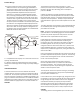
The check valve at the indoor coil will open by the ow of
refrigerant leng the now condensed liquid refrigerant bypass
the indoor expansion device. The check valve at the outdoor coil
will be forced closed by the refrigerant ow, thereby ulizing the
outdoor expansion device.
The restrictor orice used with the CA*F, CHPF and CH**FCB
coils will be forced onto a seat when running in the cooling
cycle, only allowing liquid refrigerant to pass through the orice
opening. In the heang cycle, it will be forced o the seat
allowing liquid to ow around the restrictor. A check valve is not
required in this circuit.
COOLING CYCLE
For legacy room thermostat: When the room thermostat calls
for cool, the contacts of the room thermostat close making
terminals R to Y1 & G (if thermostat calls for low stage cool), or
R to Y1, Y2 & G (if thermostat calls for high stage cool), the low
voltage circuit of the transformer is completed. Current now
ows through the magnec holding coils of the compressor
contactor (CC) and fan relay (RFC). If thermostat calls for
high stage cool, the microprocessor on the UC board will
also energize the compressor high stage solenoid to run the
compressor at full capacity.
This draws in the normally open contact CC, starng the
compressor and condenser fan motors in either low or high
stage depending on the thermostat’s demand. At the same me,
contacts RFC close, starng the indoor fan motor.
When the thermostat is sased, it opens its contacts, breaking
the low voltage circuit, causing the compressor contactor and
indoor fan relay to open, shung down the system.
If the room thermostat fan selector switch should be set on the
“on” posion, then the indoor blower would run connuously
rather than cycling with the compressor.
GSZ, ASZ, SSZ, DSZ, and VSZ models energize the reversing valve
thorough the “O” circuit in the room thermostat. Therefore,
the reversing valve remains energized as long as the thermostat
subbase is in the cooling posion. The only excepon to this is
during defrost.
For heat pumps, during cooling cycle the reversing valve is
energized as the room thermostat closes “O” terminal to R
and the microprocessor on the UC board responds to such a
condion by energizing the solenoid coil on the reversing valve.
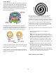
DEFROST CYCLE
The defrosng of the outdoor coil is jointly controlled by the
defrost control board and the defrost thermostat.
Solid State Defrost Control
During operaon the power to the circuit board is controlled
by a temperature sensor, which is clamped to a return bend
(3/8” coils) or a feeder tube (5 mm coils) entering the outdoor
coil. Defrost ming periods of 30, 60, or 90 minutes may be
selected by connecng the circuit board jumper to 30, 60, or 90
respecvely. Accumulaon of me for the ming period selected
starts when the sensor closes (approximately 31° F), and when
the room thermostat calls for heat. At the end of the ming
period, the unit’s defrost cycle will be iniated provided the
sensor remains closed. When the sensor opens (approximately
75° F), the defrost cycle is terminated and the ming period is
reset. If the defrost cycle is not terminated due to the sensor
temperature, a ten minute override interrupts the unit’s defrost
period. The new upgraded defrost control has a 12 minute
override interrupt.
HEATING CYCLE
The reversing valve on the gsz, SSZ, ASZ and DSZ models is
energized in the cooling cycle through the “O” terminal on the
room thermostat.
These models have a 24 volt reversing valve coil. When the
thermostat selector switch is set in the cooling posion, the “O”
terminal on the thermostat is energized all the me.
Care must be taken when selecng a room thermostat. Refer
to the installaon instrucons shipped with the product for
approved thermostats.
When the room thermostat calls for heat, the contacts of the
room thermostat close making terminals R to Y & G, the low
voltage circuit of the transformer is completed. Current now
ows through the magnec holding coils of the compressor
contactor (CC) and fan relay (RFC).
This draws in the normally open contact CC, starng the
compressor condenser fan motors. At the same me, contacts
RFC close, starng the indoor fan motor.
When the thermostat is sased, it opens its contacts, breaking
the low voltage circuit, causing the compressor contactor and
indoor fan relay to open, shung down the system.
If the room thermostat fan selector switch should be set to the
“on” posion, then the indoor blower would run connuously
rather than cycling with the compressor.
When the thermostat is sased, appropriate commands are
sent to the UC control. The compressor relay and outdoor
fan relay is de-energized. The compressor high stage solenoid
is de-energized if it was energized. The UC control sends an
appropriate command to the indoor unit to de-energize the
indoor blower motor.
SYSTEM OPERATION