
Condensing Unit & Heat Pump R410A Service Manual

123
SERVICING
1. Remove compressor discharge line strainer.
2. Remove the liquid line drier and expansion valve.
3 Purge all remaining components with dry nitrogen or carbon
dioxide unl clean.
4. Install new components including liquid line drier.
5. Braze all joints, leak test, evacuate, and recharge system.
6. Start up the unit and record the pressure drop across the
drier.
7. Connue to run the system for a minimum of twelve (12)
hours and recheck the pressure drop across the drier. Pres-
sure drop should not exceed 6 PSIG.
8. Connue to run the system for several days, repeatedly
checking pressure drop across the sucon line drier. If
the pressure drop never exceeds the 6 PSIG, the drier has
trapped the contaminants. Remove the sucon line drier
from the system.
9. If the pressure drop becomes greater, then it must be
replaced and steps 5 through 9 repeated unl it does not
exceed 6 PSIG.
NOTICE: Regardless, the cause for burnout must be determined
and corrected before the new compressor is started.
S-120 REFRIGERANT PIPING
The piping of a refrigeraon system is very important in relaon
to system capacity, proper oil return to compressor, pumping
rate of compressor and cooling performance of the evaporator.
POE oils maintain a consistent viscosity over a large temperature
range which aids in the oil return to the compressor; however,
there will be some installaons which require oil return traps.
These installaons should be avoided whenever possGible,
as adding oil traps to the refrigerant lines also increases the
opportunity for debris and moisture to be introduced into the
system. Avoid long running traps in horizontal sucon line.
S-201 CLEANING ALUMINUM COILS
This unit is equipped with an aluminum tube evaporator
coil. The safest way to clean the evaporator coil is to simply
ush the coil with water. This cleaning pracce remains as
the recommended cleaning method for both copper tube and
aluminum tube residenal cooling coils.
An alternate cleaning method is to use one of the products listed
in the technical publicaon TP-109 (shipped in the literature
bag with the unit) to clean the coils. The cleaners listed are the
only agents deemed safe and approved for use to clean round
tube aluminum coils. TP-109 is available on the web site in
Partner Link > Service Toolkit.
NOTE: Ensure coils are rinsed well aer use of any chemical
cleaners.
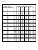
S-202 DUCT STATIC PRESSURES AND/OR STATIC PRESSURE
DROP ACROSS COILS
This minimum and maximum allowable duct stac pressure for
the indoor secons are found in the specicaons secon.
Tables are also provided for each coil, lisng quanty of air
(CFM) versus stac pressure drop across the coil.
Too great an external stac pressure will result in insucient
air that can cause icing of the coil. Too much air can cause poor
humidity control and condensate to be pulled o the evaporator
coil causing condensate leakage. Too much air can also cause
motor overloading and in many cases this constutes a poorly
designed system.
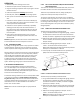
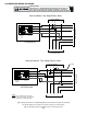
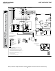
S-203 SINGLE PIECE AIR HANDLER EXTERNAL STATIC
To determine proper airow, proceed as follows:
1. Using a Inclined Manometer or Magnehelic gauge , measure
the stac pressure of the return duct at the inlet of the air
handler, this will be a negave pressure (for example-.30”wc)
2. Measure the stac pressure of the supply duct at the outlet
of the air handler, this should be a posive pressure (for
example .20”wc).
3. Add the two readings together (for example -.30”wc +
.20”wc = .50”wc total external stac pressure.
NOTE: Both readings may be taken simultaneously and read
directly on the manometer if so desired.
4. Consult proper air handler airow chart for quanty of air
(CFM) at the measured external stac pressure.
+ .20” wc
- .30” wc
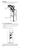
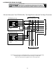
To determine proper airow, proceed as follows:
1. Using a Inclined Manometer or Magnehelic gauge, measure
the stac pressure between the outlet of the evaporator
coil and the inlet of the air handler, this will be a negave
pressure ( for example -.30”wc)
2. Measure the stac pressure of the supply duct at the outlet
of the unit, this should be a posive pressure (for example
.20”wc).
3. Add the two readings together (for example -.30”wc +
.20”wc = .50”wc total stac pressure.
NOTE: Both readings may be taken simultaneously and read
directly on the manometer if so desired.