
Condensing Unit & Heat Pump R410A Service Manual

119
CAUTION
To prevent personal injury, carefully connect and
disconnect manifold gauge hoses. Escaping liquid
refrigerant can cause burns. Do not vent refrigerant
to atmosphere. Recover during system repair
or final unit disposal.
1. Run system at least 10 minutes to allow pressure to stabilize.
2. For best results, temporarily install a thermometer on the
liquid line at the liquid line service valve and 4-6” from the
compressor on the sucon line. Ensure the thermometer
makes adequate contact and is insulated for best possible
readings. Use liquid line temperature to determine sub-cool-
ing and vapor temperature to determine superheat.
NOTE: An oponal method is to locate the thermometer
at the sucon line service valve. Ensure the thermometer
makes adequate contact and is insulated for best possible
readings.
3. Refer to the superheat table provided for proper system
superheat. Add charge to lower superheat or recover charge
to raise superheat.
Superheat Formula = Suct. Line Temp. - Sat. Suct. Temp.
EXAMPLE:
a. Sucon Pressure = 143
b. Corresponding Temp. °F. = 50
c. Thermometer on Sucon Line = 61°F.
To obtain the degrees temperature of superheat, subtract 50.0
from 61.0°F.
The dierence is 11° Superheat. The 11° Superheat would fall in
the ± range of allowable superheat.
S-109 CHECKING SUBCOOLING
Refrigerant liquid is considered subcooled when its temperature
is lower than the saturaon temperature corresponding to
its pressure. The degree of subcooling equals the degrees of
temperature decrease below the saturaon temperature at the
exisng pressure.
1. Aach an accurate thermometer or preferably a thermocou-
ple type temperature tester to the liquid line as it leaves the
condensing unit.
2. Install a high side pressure gauge on the high side (liquid)
service valve at the front of the unit.
3. Record the gauge pressure and the temperature of the line.
4. Review the technical informaon manual or specicaon
sheet for the model being serviced to obtain the design
subcooling.
5. Compare the hi-pressure reading to the "Required Liquid
Line Temperature" chart (page 108). Find the hi-pressure
value on the le column. Follow that line right to the column
under the design subcooling value. Where the two intersect
is the required liquid line temperature.
Alternately you can convert the liquid line pressure gauge
reading to temperature by nding the gauge reading in
Temperature - Pressure Chart and reading to the le, nd the
temperature in the °F. Column.
6. The dierence between the thermometer reading and pres-
sure to temperature conversion is the amount of subcooling.
Add charge to raise subcooling. Recover charge to lower
subcooling.
Subcooling Formula = Sat. Liquid Temp. - Liquid Line Temp.
EXAMPLE:
a. Liquid Line Pressure = 417
b. Corresponding Temp. °F. = 120°
c. Thermometer on Liquid line = 109°F.
To obtain the amount of subcooling subtract 109°F from 120°F.
The dierence is 11° subcooling. See the specicaon sheet or
technical informaon manual for the design subcooling range for
your unit.
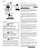
1. Remove the remote bulb of the expansion valve from the
sucon line.
2. Start the system and cool the bulb in a container of ice
water, closing the valve. As you cool the bulb, the sucon
pressure should fall and the sucon temperature will rise.
3. Next warm the bulb in your hand. As you warm the bulb,
the sucon pressure should rise and the sucon tempera-
ture will fall.
4. If a temperature or pressure change is noced, the expan-
sion valve is operang. If no change is noced, the valve is
restricted, the power element is faulty, or the equalizer tube
is plugged.
5. Capture the charge, replace the valve and drier, evacuate
and recharge.
S-112 CHECKING RESTRICTED LIQUID LINE
When the system is operang, the liquid line is warm to the
touch. If the liquid line is restricted, a denite temperature
drop will be noced at the point of restricon. In severe cases,
frost will form at the restricon and extend down the line in the
direcon of the ow.
Discharge and sucon pressures will be low, giving the
appearance of an undercharged unit. However, the unit will
have normal to high subcooling.
Locate the restricon, replace the restricted part, replace drier,
evacuate and recharge.