
Condensing Unit & Heat Pump R410A Service Manual

113
SERVICING
heater elements #3 and #4 will be turned o. On most digital/
“Y2” “W2/W3” and “W3/W4” demands will be removed.
4.5 As the temperature indoors increase, it will reach a point
where the “W2/W3” demand is sased. When this hap-
pens, the room thermostat will remove the 24Vac from “E/
W1” of the MBE/AEPF. The contacts on HR1 will open be-
tween 30 to 70 seconds and turn o the 1st and 2nd heater
elements. If the “Y2” demand is present and becomes sas-
ed the room thermostat will remove the 24Vac from “Y/Y2”
of the MBE and the blower motor will change to 60% of the
programmed cfm. The VSTB will remove the 24Vac from “Y/
Y2” at the heat pump and the outdoor fan will change to low
speed operaon. The heat pump remains on along with the
blower motor because the “Y1” demand for rst stage heat
will sll be present.
4.6 When the rst stage heat demand “Y1” is sased, the
room thermostat will remove the 24Vac from “G” and “Ylo/
Y1” of the MBE/AEPF. The VSTB removes the 24Vac from
“Ylo/Y1” at the heat pump and the compressor and outdoor
fan are turned o. The blower motor will ramp down to a
complete stop based on the me and rate programmed in
the motor control.
On heat pump units, when the room thermostat is set to the
heang mode, the reversing valve is not energized. As long as
the thermostat is set for heang, the reversing valve will be in
the de-energized posion for heang except during a defrost
cycle.
5.1 The heat pump will be on and operang in the heang
mode as described the Heang Operaon in secon 4.
5.2 The defrost control in the heat pump unit checks to see if a
defrost is needed every 30, 60 or 90 minutes of heat pump
operaon depending on the selectable seng by monitoring
the state of the defrost thermostat aached to the outdoor
coil.
5.3 If the temperature of the outdoor coil is low enough to
cause the defrost thermostat to be closed when the defrost
board checks it, the board will iniate a defrost cycle.
5.4 When a defrost cycle is iniated, the contacts of theHVDR
relay on the defrost board open and turns o the outdoor
fan. The contacts of the LVDR relay on the defrost board
closes and supplies 24Vac to “O” and “W2”. The reversing
valve is energized and the contacts on HR1 close and turns
on the electric heater(s). The unit will connue to run in this
mode unl the defrost cycle is completed.
a. For models with defrost control PCBDM133 or PCBDM160,
a 30 second compressor delay at defrost iniaon/termina-
on is oponal. As shipped from the factory, the control is
set for the delay (“DLY”), which will turn the compressor o
for 30 seconds while the reversing valve shis to/from the
cooling mode posion. To bypass the delay, which typically
reduces sound levels during defrost mode, change the pin
sengs from “DLY” to “NORM”.
5.5 When the temperature of the outdoor coil rises high
enough to causes the defrost thermostat to open, the
defrost cycle will be terminated. If at the end of the pro-
grammed 10 minute override me the defrost thermostat
is sll closed, the defrost board will automacally terminate
the defrost cycle.
S-50 CHECKING HEATER LIMIT CONTROL(S)
(OPTIONAL ELECTRIC HEATERS)
Each individual heater element is protected with an automac
rest limit control connected in series with each element to
prevent overheang of components in case of low airow. This
limit control will open its circuit at approximately 150°F. to 160°F
and close at approximately 110°F.
Disconnect ALL power before servicing.
WARNING
1. Remove the wiring from the control terminals.
2. Using an ohmmeter test for connuity across the normally
closed contacts. No reading indicates the control is open
- replace if necessary. Make sure the limits are cool before
tesng.
IF FOUND OPEN - REPLACE - DO NOT WIRE AROUND.
S-52 CHECKING HEATER ELEMENTS
Oponal electric heaters may be added, in the quanes
shown in the spec sheet for each model unit, to provide electric
resistance heang. Under no condion shall more heaters than
the quanty shown be installed.
WARNING
HIGH VOLTAGE!
Disconnect ALL power before servicing
or installing. Multiple power sources
may be present. Failure to do so may
cause property damage, personal injury
or death.
1. Disassemble and remove the heang element(s).
2. Visually inspect the heater assembly for any breaks in the
wire or broken insulators.
3. Using an ohmmeter, test the element for connuity - no
reading indicates the element is open. Replace as necessary.
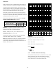
S-60 ELECTRIC HEATER (OPTIONAL ITEM)
Oponal electric heaters may be added, in the quanes shown
in the specicaons secon, to provide electric resistance
heang. Under no condion shall more heaters than the
quanty shown be installed.
The low voltage circuit in the air handler is factory wired and
terminates at the locaon provided for the electric heater(s). A
minimum of eld wiring is required to complete the installaon.