
Condensing Unit & Heat Pump R410A Service Manual

110
SERVICING
mostat will remove the 24Vac from “E/W1” and the VSTB
rebetween 30 to 70 seconds and turn o the heater ele-
ment(s) and the blower motor ramps down to a complete
stop.
MBE/AEPF WITH SINGLE STAGE
When used with a single stage GSZ, SSZ, ASZ, or VSZ heat
pumps, dip switch #4 must be set to the ON posion on
the VSTB inside the MBE. The “Y” output from the indoor
thermostat must be connected to the yellow wire labeled “Y/
Y2” inside the wire bundle marked “Thermostat” and the yellow
wire labeled “Y/Y2” inside the wire bundle marked “Outdoor
Unit” must be connected to “Y” at the heat pump. The orange
jumper wire from terminal “Y1” to terminal “O” on the VSTB
inside the MBE/AEPF must be removed.
3.0 COOLING OPERATION
On heat pump units, when the room thermostat is set to the
cooling mode, 24Vac is supplied to terminal “O” of the VSTB
inside the MBE/AEPF unit. The VSTB will supply 24Vac to “O” at
the heat pump to energize the reversing valve. As long as the
thermostat is set for cooling, the reversing valve will be in the
energized posion for cooling.
3.1 On a demand for cooling, the room thermostat energizes
“G” and “Y” and 24Vac is supplied to terminals “G” and “Y/
Y2” of the MBE/AEPF unit. The VSTB will turn on the blower
motor and the motor will ramp up to the speed programmed
in the motor based on the sengs of dip switch 5 and 6.
The VSTB will supply 24Vac to “Y” at the heat pump.
3.2 The heat pump is turned on in the cooling mode.
3.3 When the cooling demand is sased, the room thermostat
removes the 24Vac from “G” and “Y/Y2” of the MBE/AEPF
and the VSTB removes the 24Vac from “Y” at the heat pump.
The heat pump is turned o and the blower motor will ramp
down to a complete stop based on the me and rate pro-
grammed in the motor.
On heat pump units, when the room thermostat is set to the
heang mode, the reversing valve is not energized. As long
as the thermostat is set for heang, the reversing valve will
be in the de-energized posion for heang except during a
defrost cycle. Some installaons may use one or more outdoor
thermostats to restrict the amount of electric heat that is
available above a preset ambient temperature. Use of oponal
controls such as these can change the operaon of the electric
heaters during the heang mode. This sequence of operaon
does not cover those applicaons.
4.1 On a demand for rst stage heat with heat pump units,
the room thermostat energizes “Y” and “G” and 24Vac is
supplied to “G” and “Y/Y2” of the MBE/AEPF. The VSTB will
turn on the blower motor and the motor will ramp up to the
speed programmed in the motor based on the sengs of
dip switch 1 and 2. The VSTB will supply 24Vac to “Y” at the
heat pump and the heat pump is turned on in the heang
mode.
4.2 If the rst stage heat demand cannot be sased by the
heat pump, the temperature indoors will connue to drop.
The room thermostat will then energize terminal “W2” for
second stage heat and 24Vac will be supplied to “E/W1” of
the MBE/
AEPF. The VSTB will supply 24Vac to heat sequencer, HR1, on
the electric heater assembly.
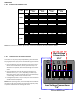
4.3 HR1 contacts M1 and M2 will close within 10 to 20 seconds
and turn on heater element #1. At the same me, if the
heater assembly contains a second heater element, HR1
will contain a second set of contacts, M3 and M4, which will
close to turn on heater element #2.
NOTE: If more than two heater elements are on the heater
assembly, it will contain a second heat sequencer, HR2, which
will control the 3rd and 4th heater elements if available. For the
3rd and 4th heater elements to operate on a third stage heat
demand, the PJ4 jumper on the VSTB inside the MBE/AEPF
must be cut. If the second stage heat demand, “W2”, cannot
be sased by the heat pump, the temperature indoors will
connue to drop. The room thermostat will then energize “W3”
and 24Vac will be supplied to “W/W2” of the MBE/AEPF. The
VSTB will supply 24Vac to HR2 on the electric heater assembly.
When the “W3” demand is sased, the room thermostat
will remove the 24Vac from “W/W2” of the MBE/AEPF. The
contacts on HR2 will open between 30 to 70 seconds and
heater elements #3 and #4 will be turned o. On most digital/
and “W3” demands will be removed.
4.4 As the temperature indoors increase, it will reach a point
where the second stage heat demand, “W2”, is sased.
When this happens, the room thermostat will remove the
24Vac from “E/W1” of the MBE/AEPF. The contacts on HR1
will open between 30 to 70 seconds and turn o both heater
element(s). The heat pump remains on along with the
blower motor because the “Y” demand for rst stage heat
will sll be present.
4.5 When the rst stage heat demand “Y” is sased, the room
thermostat will remove the 24Vac from “G” and “Y/Y2” of
the MBE/AEPF. The VSTB removes the 24Vac from “Y” at
the heat pump and the heat pump is turned o. The blower
motor will ramp down to a complete stop based on the me
and rate programmed in the motor control.
5.0 DEFROST OPERATION
On heat pump units, when the room thermostat is set to the
heang mode, the reversing valve is not energized. As long as
the thermostat is set for heang, the reversing valve will be in
the de-energized posion for heang except during a defrost
cycle.
5.1 The heat pump will be on and operang in the heang
mode as described the Heang Operaon in secon 4.
5.2 The defrost control in the heat pump unit checks to see if a
defrost is needed every 30, 60 or 90 minutes of heat pump
operaon depending on the selectable seng by monitoring
the state of the defrost thermostat aached to the outdoor
coil.
5.3 If the temperature of the outdoor coil is low enough to
cause the defrost thermostat to be closed when the defrost
board checks it, the board will iniate a defrost cycle.
5.4 When a defrost cycle is iniated, the contacts of the HVDR