
Condensing Unit & Heat Pump R410A Service Manual

107
SERVICING
3. Reverse rotaon will result in substanally reduced amp
draw from tabulated values.
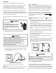
To correct improper rotaon, switch any two power supply leads
at the outdoor unit contactor.
The 3-phase scroll compressors are direcon of rotaon
sensive. They will rotate in either direcon depending on the
phasing of the power. There is no negave impact on durability
caused by operang 3-phase compressors in reversed rotaon.
The compressor’s internal protector will trip, de-energizing the
compressor. Connued operaon of 3-phase scroll compressors
with the rotaon reversed will contribute to compressor failure.
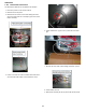
All 3-phase scroll compressors should be checked for correct
phase rotaon.
The crankcase heater must be energized a minimum of four (4)
hours before the condensing unit is operated.
Crankcase heaters are used to prevent migraon or
accumulaon of refrigerant in the compressor crankcase during
the o cycles and prevents liquid slugging or oil pumping on
start up.
A crankcase heater will not prevent compressor damage due to a
oodback or over charge condion.
Disconnect ALL power before servicing.
WARNING
1. Disconnect the heater lead in wires.
2. Using an ohmmeter, check heater connuity - should test
connuous. If not, replace.
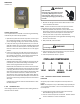
NOTE: The posive temperature coecient crankcase heater is
a 40 wa 265 voltage heater. The cool resistance of the heater
will be approximately 1800 ohms. The resistance will become
greater as the temperature of the compressor shell increases.
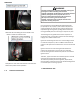
Occasionally the reversing valve may sck in the heang or
cooling posion or in the mid-posion.
When stuck in the mid-posion, part of the discharge gas from
the compressor is directed back to the sucon side, resulng in
excessively high sucon pressure. An increase in the sucon line
temperature through the reversing valve can also be measured.
Check operaon of the valve by starng the system and
switching the operaon from COOLING to HEATING cycle.
If the valve fails to change its posion, test the voltage (24V)
at the valve coil terminals, while the system is on the COOLING
cycle.
If no voltage is registered at the coil terminals, check the
operaon of the thermostat and the connuity of the
connecng wiring from the “O” terminal of the thermostat to
the unit.
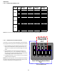
To check the defrost control for proper sequencing, proceed as
follows: With power ON; unit not running.
1. Jumper defrost thermostat by placing a jumper wire across
the terminals “DFT” and “R”/”R-DFT” at defrost control
board.
2. Connect jumper across test pins on defrost control board.
3. Set thermostat to call for heang. System should go into
defrost within 21 seconds.
4. Immediately remove jumper from test pins.
5. Using VOM check for voltage across terminals “C & O”. Me-
ter should read 24 volts.
6. Using VOM check for voltage across fan terminals DF1 and
DF2 on the board. You should read line voltage (208-230
VAC) indicang the relay is open in the defrost mode.
7. Using VOM check for voltage across “W”/”W2” & “C” termi-
nals on the board. You should read 24 volts.
8. If not as above, replace control board.
9. Set thermostat to o posion and disconnect power before
removing any jumpers or wires.
NOTE: Remove jumper across defrost thermostat before
returning system to service.
1. Install a thermocouple type temperature test lead on the
tube adjacent to the defrost control. Insulate the lead point
of contact.
2. Check the temperature at which the control closes its
contacts by lowering the temperature of the control. Part #
0130M00009P which is used on 2 and 2.5 ton units should
close at 34°F ± 5°F. Part # 0130M00001P or B1370803 which
is used on 3 thru 5 ton units should close at 31°F ± 3°F.
3. Check the temperature at which the control closes its
contacts by lowering the temperature of the control. Part #
0130M00085, which is used onunits with 5 mm coils, should
close at 30°F ± 5°F.
4. Check the temperature at which the control opens its
contacts by raising the temperature of the control. Part
#0130M00009P which is used on 2 and 2.5 ton units should
open at 60°F ± 5°F. Part # 0130M00001P or B1370803 which
is used on 3 thru 5 ton units should open at 75°F ± 6°F.
5. Check the temperature at which the control opens its
contacts by raising the temperature of the control. Part #
0130M00085, which is used on units with 5 mm coils, should
open at 60°F ± 5°F.
6. If not as above, replace control.
SEQUENCE OF OPERATION
MBR/AR*F WITH SINGLE STAGE CONDENSERS
1.1 On a demand for cooling, the room thermostat energizes