
Condensing Unit & Heat Pump R410A Service Manual

105
SERVICING
Each compressor is equipped with an internal overload.
The line break internal overload senses both motor amperage
and winding temperature. High motor temperature or
amperage heats the disc causing it to open, breaking the
common circuit within the compressor on single phase units.
Heat generated within the compressor shell, usually due to
recycling of the motor, high amperage or insucient gas to cool
the motor, is slow to dissipate. Allow at least three to four hours
for it to cool and reset, then retest.
Fuse, circuit breaker, ground fault protecve device, etc. has not
tripped -
WARNING
HIGH VOLTAGE!
Disconnect ALL power before servicing
or installing. Multiple power sources
may be present. Failure to do so may
cause property damage, personal injury
or death.
1. Remove the leads from the compressor terminals.
WARNING
Hermetic compressor electrical terminal venting can
be dangerous. When insulating material which
supports a hermetic compressor or electrical terminal
suddenly disintegrates due to physical abuse or as a
result of an electrical short between the terminal and
the compressor housing, the terminal may be
expelled, venting the vapor and liquid contents of the
compressor housing and system.
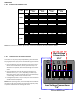
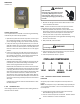
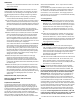
2. Using an ohmmeter, test connuity between terminals S-R,
C-R, and C-S, on single phase units or terminals T2, T2 and
T3, on 3 phase units.
S
R
C
COMP
OHMMETER
TESTING COMPRESSOR WINDINGS
If either winding does not test connuous, replace the
compressor.
NOTE: If an open compressor is indicated, allow ample me for
the internal overload to reset before replacing compressor.
S-17B Ground Test
If fuse, circuit breaker, ground fault protecve device, etc., has
tripped, this is a strong indicaon that an electrical problem
exists and must be found and corrected. The circuit protecve
device rang must be checked, and its maximum rang should
coincide with that marked on the equipment nameplate.
With the terminal protecve cover in place, it is acceptable to
replace the fuse or reset the circuit breaker ONE TIME ONLY to
see if it was just a nuisance opening. If it opens again, DO NOT
connue to reset.
Disconnect all power to unit, making sure that all power legs
are open.
1. DO NOT remove protecve terminal cover. Disconnect the
three leads going to the compressor terminals at the nearest
point to the compressor.
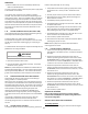
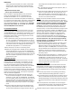
2. Idenfy the leads and using an ohmmeter on the R x 10,000
scale or the highest resistance scale on your ohmmeter
check the resistance between each of the three leads sepa-
rately to ground (such as an unpainted tube on the compres-
sor).
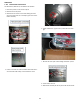
3. If a ground is indicated, then carefully remove the compres-
sor terminal protecve cover and inspect for loose leads or
insulaon breaks in the lead wires.
4. If no visual problems indicated, carefully remove the leads at
the compressor terminals.
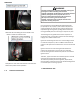
5. Carefully retest for ground, directly between compressor
terminals and ground.
6. If ground is indicated, replace the compressor. The resistance
reading should be innity. If there is any reading on meter,
there is some connuity to ground and compressor should
be considered defecve.
OHMMETER
WARNING
Damage can occur to the glass embedded terminals if
the leads are not properly removed. This can result in
terminal and hot oil discharging.
S-17C Unloader Test Procedure
A nominal 24-volt direct current coil acvates the internal
unloader solenoid. The input control circuit voltage must be 18
to 28 volt ac. The coil power requirement is 20 VA. The external
electrical connecon is made with a molded plug assembly. This
plug contains a full wave recer to supply direct current to the