
Instructions / Assembly

39
OFF
100% CFM 100% CFM
1 min
OFF
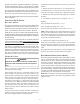
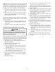
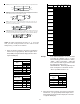
Figure 50
• provides only an OFF delay of one (1) minute at 100% of the cooling demand airflow.
Profile A
50% CFM
1/2 min
100% CFM
100% CFM
1 min
OFF
OFF
Figure 51
• ramps up to full cooling demand airflow by first stepping up to 50% of the full
demand for 30 seconds. The motor then ramps to 100% of the required airflow. A one (1)
minute OFF delay at 100% of the cooling airflow is provided.
Profile B
100% CFM
OFF
OFF
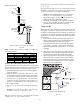
• ramps up to 85% of the full cooling demand airflow and operates there for
approximately 7 1/2 minutes. The motor then steps up to the full demand airflow. Profile C
also has a one (1) minute 100% OFF delay.
Profile C
Figure 52
OFF
OFF
• ramps up to 50% of the demand for 1/2 minute, then ramps to 85% of the full
cooling demand airflow and operates there for approximately 7 1/2 minutes. The motor
then steps up to the full demand airflow. Profile D has a 1/2 minute at 50% airflow OFF delay.
Profile D
Figure 53
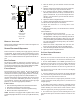
NOTE: To enable adjustments and select -5, 5, -10 or 10%
trim, you must set dip switch S5-2 to ON. If S5-2 is in the
OFF position, you will receive 0% trim.
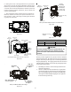
7. Select the desired “heating” speed tap by positioning
switches S4- 3,4 appropriately. Refer to figure above.
Verify CFM by noting the number displayed on the dual 7-
segment LED display.
12
AOFFOFF
BONOFF
COFFON
D* ON ON
Switch Bank: S3
Cooling Speed
Taps
DIP Sw itch No.
(*Indicates factory setting)
34
+ 5%* OFF OFF
- 5% ON OFF
+ 10% OFF ON
- 10% ON ON
Sw itch Bank: S3
Adjust Taps
DIP Sw itch No.
(*Indicates factory setting)
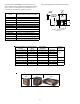
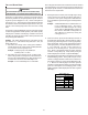
Example: If the *MVC960804CN** is set for 1210 CFM
on cooling, the “ADJUST” is set to “+” (plus).
The four heating speeds available are “A Plus”,
“B Plus”, “C Plus”, and “D Plus”. “A Plus” has
a rise of 46°F for both stages which is within
the 30-60°F rise range for the *
*MVC960804CN**. This setting will keep elec-
trical consumption to a minimum. Set the
“Heat” speed DIP switches to “A”.
34
AOFFOFF
B* ON OFF
COFFON
DONON
(Indicates factory setting)
Sw itch Bank S4
Heating
Airflow
DIP Sw itch No.
8. Select the desired “heating” speed tap by positioning
switches S-4, 3, 4, appropriately. Refer to figure above.
Verify CFM by noting the number displayed on the dual
7-segment LED display.
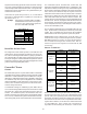
Model Tap
Low
Stage
Cool
High
Stage
Cool
Low Stage
Heat
High
Stage
Heat
A
403 596 422 494
B
527 796 471 553
C
675 974 521 601
D
803 1192 574 676
A
398 599 667 953
B
557 817 740 1059
C
696 1007 808 1158
D
810 1212 881 1260
A
403 629 855 1202
B
540 806 923 1316
C
705 1023 1033 1389
D
819 1230 1063 1396
A
513 789 867 1228
B
660 967 939 1337
C
791 1182 1016 1430
D
913 1375 1077 1516
A
564 820 1256 1818
B
784 1133 1292 1870
C
982 1464 1316 1910
D
1259 1736 1358 1957
A
597 895 1205 1683
B
852 1156 1230 1727
C
1031 1459 1256 1763
D
1282 1864 1281 1796
A
547 867 1329 1891
B
831 1160 1362 1940
C
1020 1467 1390 1968
D
1278 1910 1440 2028
A
449 655 682 957
B
569 807 750 1059
C
716 998 820 1155
D
854 1207 888 1251
A
433 656 687
938
B
541 790 751
950
C
686 972 814 986
D
806 1195 874 992
A 405 624 758 1057
B 549 808 815 1146
C 678 994 882 1256
D 784 1177 946 1349
A
556 837 889 1234
B
714 1022 944 1325
C
838 1206 1019 1442
D
991 1475 1068 1528
A
524 784 1209 1759
B
744 1078 1249 1797
C
927 1388 1277 1840
D
1185 1766 1300 1881
A
540 854 1284 1744
B
870 1123 1310 1827
C
1000 1399 1350 1860
D
1235 1804 1388 1918
*CVC961005CN*
*MVC960403BN*
*CVC960403BN*
*CVC961205DN*
*MVC961205DN*
*CVC960603BN
*CVC960803BN
*CVC960804CN*
*MVC960603BN*
*MVC960803BN*
*MVC960804CN*
*MVC961005CN*
*MVC961005DN*