
Installation Instructions

29
A
IR
F
LOW
D
ATA
TAP Low
Stage
Cool
High
Stage
Cool
Low
Stage
Heat
High
Stage
Heat
MODEL
TAP Low
Stage
Cool
High
Stage
Cool
Low
Stage
Heat
High
Stage
Heat
A 412 631 784 1107
A B 468 698 735 1012
B 570 839 851 1198 B 584 847 804 1098
C 718 1050 922 1316 C 738 1034 874 1201
D 842 1239 981 1407
D
872 1253 934 1310
A 423 643 690 937 A 390 600 875 1250
B 582 782 743 1045 B 520 800 945 1350
C 690 982 807 1155 C 715 1100 1015 1450
D 802 1200 870 1254 D 910 1400 1085 1550
A 532 817 976 1401 A
465 730 735 1012
B 732 1123 1048 1495 B 584 878 804 1098
C 942 1445 1121 1579 C 780 1056 874 1201
D 1197 1861 1192 1684 D 924 1224 934 1310
A 556 848 1150 1591
A 588 857 908 1234
B 838 1177 1188 1646 B 742 1051 986 1365
C 1031 1480 1211 1702 C
878 1284 1061 1501
D 1299 1881 1284 1790 D 1049 1616 1142 1618
A 520 800 1050 1500
B 715 1100 1120 1600
C 910 1400 1190 1700
D 1170 1800 1260 1800
Tap
S3- 1 S3- 2 S3- 3 S3- 4 S4-1 S4-2 S4- 3 S4-4
A
582 830 1386 1998
A
OFF OFF OFF OFF OFF OFF OFF OFF
B 786 1139 1405 2007
B
ON OFF ON OFF ON OFF OFF ON
C 1047 1561 1415 2022
C
OFF ON OFF ON OFF ON OFF OFF
D 1326 1966 1435 2047
D
ON ON ON ON ON ON OFF ON
A 520 800 1210 1725
Profile
B
715 1100 1225 1750
A
C 910 1400 1245 1775
B D
1170 1800 1260 1800
C
D
60 sec @100%
---- 7.5 min
@
82%
60 sec @100%
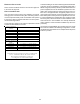
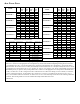
To Set Airflow: (1) Select model and desired High Stage Cooling Airflow. Determine the corresponding tap (A, B, C, or D). Set dip
switches S3-1* and S3-2* to the appropriate ON / OFF positions. (2) Select model and desired High Stage Heating Airflow. Determine
the corresponding tap (A, B, C, or D). Set dip switches S4-3* and S4-4* to the appropriate ON / OFF positions. (3) Selecting Airflow
Adjustment Factor: For 0% trim set S5-2* to OFF (trim disabled). If trim is desired set S5-2* to ON (trim enabled) and set S3-3* and S3-
4* to appropriate ON / OFF positions. Tap A is +5%, Tap B is -5%, Tap C is +10%, Tap D is -10%. To Set Comfort Mode: Select Desired
Comfort Mode profile (see profiles above). Set dip switches S4-1* and S4-2* to the appropriate ON / OFF positions. Dehumidification:
To enable, set switch S5-1* to ON. Cooling airflow will be reduced to 85% of nominal value during cool call. To disable, set switch S5-
1* to OFF. Continuous Fan Speed: Set dip switches S5-3* and S5-4* to select one of 4 continuous fan speeds (25%, 50%, 75%, or
100%). " See installation manual for details"*the “S” number refers to one of four labeled dip switch section each containing 4 individual
dip switches. The following number refers to the individual labeled dip switch within that section
0140F02298-A
30 sec
@
50% 7.5 min
@
82%
30 sec @ 50%
*CVC80805C*** *MVC80803B***
*MVC80804C***
*MVC80805C***
Speed Selection Dip Switches
Cool Selection
Switches
Adjust Selection
Switches
Profile Selection
Switches
Heat Selection
Switches
*MVC80805D***
*MVC81005C***
*CVC80803B***
*CVC80603B***
MODEL
*MVC80603B***
*MVC80604B***
*CVC81005C***
----
60 sec @100%
Pre-Run
Off Delay
Short Run
----
---- 30sec
@
50%