
Condensing Unit & Heat Pump R410A Service Manual

97
value of the capacitor).
5. If you read a signicantly lower capacitance or none at all,
then capacitor is dead and must be replaced.
The auto reset fan motor overload is designed to protect the
motor against high temperature and high amperage condions
by breaking the common circuit within the motor, similar to the
compressor internal overload. However, heat generated within
the motor is faster to dissipate than the compressor, allow at
least 45 minutes for the overload to reset, then retest.
WARNING
HIGH VOLTAGE!
Disconnect ALL power before servicing
or installing. Multiple power sources
may be present. Failure to do so may
cause property damage, personal injury
or death.
1. Remove the motor leads from its respecve connecon
points and capacitor (if applicable).
2. Check the connuity between each of the motor leads.
3. Touch one probe of the ohmmeter to the motor frame
(ground) and the other probe in turn to each lead.
If the windings do not test connuous or a reading is obtained
from lead to ground, replace the motor.
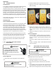
An ECM is an Electronically Commutated Motor which oers
many signicant advantages over PSC motors. The ECM has
near zero rotor loss, synchronous machine operaon, variable
speed, low noise, and programmable air ow. Because of
the sophiscated electronics within the ECM motor, some
technicians are inmated by the ECM motor; however, these
fears are unfounded. GE oers two ECM motor testers, and with
a VOM meter, one can easily perform basic troubleshoong on
ECM motors. An ECM motor requires power (line voltage) and
a signal (24 volts) to operate. The ECM motor stator contains
permanent magnet. As a result, the sha feels “rough” when
turned by hand. This is a characterisc of the motor, not an
indicaon of defecve bearings.
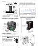
Line Voltage now present.
WARNING
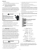
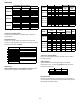
1. Disconnect the 5-pin connector from the motor.
2. Using a volt meter, check for line voltage at terminals #4 &
#5 at the power connector. If no voltage is present:
3. Check the unit for incoming power See secon S-1.
4. Check the control board, See secon S-40.
5. If line voltage is present, reinsert the 5-pin connector and
remove the 16-pin connector.
6. Check for signal (24 volts) at the transformer.
7. Check for signal (24 volts) from the thermostat to the “G”
terminal at the 16-pin connector.
8. Using an ohmmeter, check for connuity from the #1 & #3
(common pins) to the transformer neutral or “C” thermostat
terminal. If you do not have connuity, the motor may func-
on erracally. Trace the common circuits, locate and repair
the open neutral.
9. Set the thermostat to “Fan-On”. Using a voltmeter, check for
24 volts between pin # 15 (G) and common.
10.Disconnect power to compressor. Set thermostat to call for
cooling. Using a voltmeter, check for 24 volts at pin # 6 and
or #14.
11.Set the thermostat to a call for heang. Using a voltmeter,
check for 24 volts at pin #2 and/or #11.
1
2
3
4
5
Lines 1 and 2 will be connected
for 12OVAC Power Connector
applications only
Gnd
AC Line Connection
AC Line Connection
}
11
1 9
2
3
4
5
6
7
8 16
15
14
13
12
10
OUT - OUT +
ADJUST +/-
G (FAN)
Y1 Y/Y2
COOL
EM Ht/W2
DELAY
24 Vac (R)
COMMON2
HEAT
W/W1
BK/PWM (SPEED)
COMMON1 O (REV VALVE)
16-PIN ECM HARNESS CONNECTOR
If you do not read voltage and connuity as described, the
problem is in the control or interface board, but not the motor.
If you register voltage as described , the ECM power head is
defecve and must be replaced.
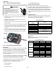
S-15 CHECKING CAPACITOR
A run capacitor is wired across the auxiliary and main windings
of a single phase permanent split capacitor motor. The
capacitors primary funcon is to reduce the line current while
greatly improving the torque characteriscs of a motor. This is
accomplished by using the 90° phase relaonship between the
capacitor current and voltage in conjuncon with the motor
windings, so that the motor will give two phase operaon when
connected to a single phase circuit. The capacitor also reduces
the line current to the motor by improving the power factor.
The line side of this capacitor is marked with “COM” and is wired
to the line side of the circuit.
SCROLL COMPRESSOR MODELS
In most cases hard start components are not required on Scroll
compressor equipped units due to a non-replaceable check
valve located in the discharge line of the compressor. However,
in installaons that encounter low lock rotor voltage, a hard
start kit can improve starng characteriscs and reduce light
dimming within the home. Only hard start kits approved by
Amana® brand or Copeland should be used. “Kick Start” and/or
“Super Boost” kits are not approved start assist devices.
The discharge check valve closes o high side pressure to the
compressor aer shut down allowing equalizaon through the
scroll anks. Equalizaon requires only about 1/2 second.
To prevent the compressor from short cycling, a Time Delay
Relay (Cycle Protector) has been added to the low voltabe
circuit.
WARNING
HIGH VOLTAGE!
Disconnect ALL power before servicing
or installing. Multiple power sources
may be present. Failure to do so may
cause property damage, personal injury
or death.
Check for Digital Test
1. Set the meter on Ohm range (Set it at lease 1000 Ohm
=1k).
WARNING
Discharge capacitor through a 20 to 30 OHM
resistor before handling.
WARNING
SERVICING