
Condensing Unit & Heat Pump R410A Service Manual

87
SERVICING
3. No voltage indicates the trouble is in the thermostat or wir-
ing.
4. Check the connuity of the thermostat and wiring. Repair or
replace as necessary.
NOTE: Consideraon must be given to how the heaters are
wired (O.D.T. and etc.). Also safety devices must be checked for
connuity.
S-4 Checking Transformer And Control Circuit
WARNING
HIGH VOLTAGE!
Disconnect ALL power before servicing
or installing. Multiple power sources
may be present. Failure to do so may
cause property damage, personal injury
or death.
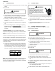
A step-down transformer (208/240 volt primary to 24 volt
secondary) is provided with each indoor unit. This allows ample
capacity for use with resistance heaters. The outdoor secons
do not contain a transformer (see note below).
Disconnect ALL power before servicing.
WARNING
1. Remove control panel cover, or etc., to gain access to trans-
former.
With power ON:
Line Voltage now present.
WARNING
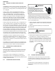
2. Using a voltmeter, check voltage across secondary voltage
side of transformer (R to C).
3. No voltage indicates faulty transformer, bad wiring, or bad
splices.
4. Check transformer primary voltage at incoming line voltage
connecons and/or splices.
5 If line voltage available at primary voltage side of transform-
er and wiring and splices good, transformer is inoperave.
Replace.
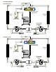
S-7 CHECKING CONTACTOR AND/OR RELAYS
WARNING
HIGH VOLTAGE!
Disconnect ALL power before servicing
or installing. Multiple power sources
may be present. Failure to do so may
cause property damage, personal injury
or death.
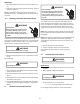
The compressor contactor and other relay holding coils are
wired into the low or line voltage circuits. When the control
circuit is energized, the coil pulls in the normally open contacts
or opens the normally closed contacts. When the coil is de-
energized, springs return the contacts to their normal posion.
NOTE: Most single phase contactors break only one side of the
line (L1), leaving 115 volts to ground present at most internal
components.
NOTE: The compressor contactor/relay in ComfortNetTM ready
equipment is fully integrated into the unitary (UC) control.
The compressor contactor/relay coil on the UC control is non-
serviceable.
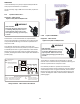
1. Remove the leads from the holding coil.
2. Using an ohmmeter, test across the coil terminals.
If the coil does not test connuous, replace the relay or
contactor.
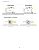
S-8 CHECKING CONTACTOR CONTACTS
Disconnect ALL power before servicing.
WARNING
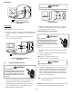
SINGLE PHASE:
1. Disconnect the wire leads from the terminal (T) side of the
contactor.
2. With power ON, energize the contactor.
Line Voltage now present.
WARNING
3. Using a voltmeter, test across terminals.
A. L2 - T1 - No voltage indicates CC1 contacts open.
If a no voltage reading is obtained - replace the contactor.