
Condensing Unit & Heat Pump R410A Service Manual

106
SERVICING
unloader coil.
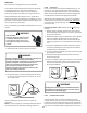
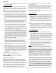
UNLOADER SOLENOID
(Molded Plug)
Unloader Test Procedure
If it is suspected that the unloader is not working, the following
methods may be used to verify operaon.
1. Operate the system and measure compressor current. Cycle
the unloader ON and OFF at 10 second intervals. The com-
pressor amperage should go up or down at least 25 percent.
2. If step one does not give the expected results, shut unit o.
Apply 18 to 28 volt ac to the unloader molded plug leads and
listen for a click as the solenoid pulls in. Remove power and
listen for another click as the unloader returns to its original
posion.
3. If clicks can’t be heard, shut o power and remove the con-
trol circuit molded plug from the compressor and measure
the unloader coil resistance. The resistance should be 32 to
60 ohms, depending on compressor temperature.
4. Next check the molded plug.
A.Voltage check: Apply control voltage to the plug wires (18
to 28 volt ac). The measured dc voltage at the female con-
nectors in the plug should be around 15 to 27 vdc.
B.Resistance check: Measure the resistance from the end of
one molded plug lead to either of the two female connectors
in the plug. One of the connectors should read close to zero
ohms while the other should read innity. Repeat with other
wire. The same female connector as before should read
zero while the other connector again reads innity. Reverse
polarity on the ohmmeter leads and repeat. The female con-
nector that read innity previously should now read close to
zero ohms.
C.Replace plug if either of these test methods doesn’t show
the desired results.
If the voltage, capacitor, overload and motor winding test fail to
show the cause for failure:
WARNING
HIGH VOLTAGE!
Disconnect ALL power before servicing
or installing. Multiple power sources
may be present. Failure to do so may
cause property damage, personal injury
or death.
1. Remove unit wiring from disconnect switch and wire a test
cord to the disconnect switch.
NOTE: The wire size of the test cord must equal the line wire
size and the fuse must be of the proper size and type.
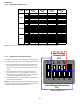
2. With the protecve terminal cover in place, use the three
leads to the compressor terminals that were disconnected
at the nearest point to the compressor and connect the
common, start and run clips to the respecve leads.
3. Connect good capacitors of the right MFD and voltage rang
into the circuit as shown.
4. With power ON, close the switch.
Line Voltage now present.
WARNING
A. If the compressor starts and connues to run, the cause for
failure is somewhere else in the system.
B. If the compressor fails to start - replace.
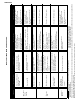
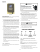
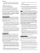
COPELAND COMPRESSOR
03 A 12345 L
YEAR
MONTH
SERIAL
NUMBER
PLANT
ROTATION
Verify the proper rotaon of Copeland scroll compressors as
follows:
NOTE: The compressor may run backwards (noisy operaon) for
1 or 2 seconds at shutdown. This is normal and does not harm
the compressor.
1. Install gauges and verify that the sucon pressure drops
while the discharge pressure increases.
2. Listen for normal compressor sound levels. Reverse rotaon
results in elevated or unusual sound levels.