
Installation Instructions

31
12
A* OFF OFF
BONOFF
COFFON
DONON
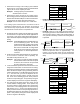
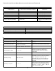
Switch Bank: S4
DIP Switch No.
(*Indicates factory setting)
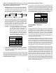
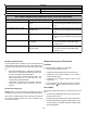
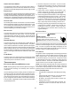
Ramping
Profiles
• Profile A provides only an OFF delay of one (1) minute
at 100% of the cooling demand airflow.
OFF
100% CFM 100% CFM
1 min
OFF
• Profile B ramps up to full cooling demand airflow by
first stepping up to 50% of the full demand for 30 seconds.
The motor then ramps to 100% of the required airflow. A
one (1) minute OFF delay at 100% of the cooling airflow
is provided.
50% CFM
1/2 min
100% CFM
100% CFM
1 min
OFF
OFF
• Profile C ramps up to 85% of the full cooling demand
airflow and operates there for approximately 7 1/2
minutes. The motor then steps up to the full demand
airflow. Profile C also has a one (1) minute 100% OFF
delay.
100% CFM
OFF
OFF
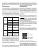
12
AOFFOFF
BONOFF
COFFON
D* ON ON
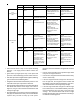
Switch Bank: S3
Cooling
Airflow
DIP Switch No.
(*Indicates factory setting)
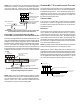
34
+5%* OFF OFF
-5% ON OFF
10% OFF ON
-10% ON ON
Switch Bank: S3
Adjust Taps
DIP Switch No.
(*Indicates factory setting)
1. Determine the tonnage of the cooling system installed
with the furnace. If the cooling capacity is in BTU/hr divide
it by 12,000 to convert capacity to TONs.
Example: Cooling Capacity of 30,000 BTU/hr.
30,000/12,000 = 2.5 Tons
2. Determine the proper air flow for the cooling system.
Most cooling systems are designed to work with air flows
between 350 and 450 CFM per ton. Most manufacturers
recommend an air flow of about 400 CFM per ton.
Example: 2.5 tons X 400 CFM per ton = 1000 CFM
The cooling system manufacturer’s instructions must be
checked for required air flow. Any electronic air cleaners or
other devices may require specific air flows, consult installa-
tion instructions of those devices for requirements.
3. Knowing the furnace model, locate the high stage cooling
air flow charts in the Specification Sheet applicable to
your model. Look up the cooling air flow determined in
step 2 and find the required cooling speed and adjustment
setting.
Example: A *MVC80604BX furnace installed with a 2.5
ton air conditioning system. The air flow
needed is 1000 CFM. Looking at the cooling
speed chart for *MVC80604BX, find the air
flow closest to 1000 CFM. A cooling airflow
of 990 CFM can be attained by setting the
cooling speed to “C” and the adjustment to
-10% trim.
4. Continuous fan speeds that provide 25, 50, 75 and 100%
of the furnace’s maximum airflow capability are
selectable via dip switches S5- 3, 4.
Example: If the furnace’s maximum airflow capability
is 2000 CFM and 25% continuous fan speed
is selected, the continuous fan speed will
be 0.25 x 2000 CFM = 500 CFM.
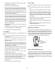
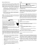
5. Locate the blower speed selection DIP switches on the
integrated control module. Select the desired “cooling”
speed tap by positioning switches 1 and 2 appropriately.
Select the desired “adjust” tap by positioning switches
3 and 4 appropriately. To enable adjustments and select
-5, 5, -10 or 10% trim, you must set dipswitch S5-2 to
ON. If S5-2 is in the OFF position, you will receive 0%
trim. Refer to the following figure for switch positions
and their corresponding taps. Verify CFM by noting the
number displayed on the dual 7-segment LED display.
6. The multi-speed circulator blower also offers several
custom ON/OFF ramping profiles. These profiles may
be used to enhance cooling performance and increase
comfort level. The ramping profiles are selected using
DIP switches S4- 1, 2. Refer to the following figure for
switch positions and their corresponding taps. Refer to
the bullet points below for a description of each ramping
profile. Verify CFM by noting the number displayed on
the dual 7-segment LED display.