
Service Manual


SERVICING
39
S-125 THERM OSTATIC EXPANSION VALVE
The expansion valve is designed to cont rol the rateof liquid refrig-
erant flow into an evaporator coil in exact proportion to the rate
of evaporation of the refrigerant in t he coil. The amount of refrig-
erant entering t he coil is regulated since the valve responds to
temperature of the refrigerant gas leaving the coil (feeler bulb
contact) and the pressure of the refrigerant in the coil. This regu-
lation of the flow prevent s the ret urn of liquid refrigerant to the
compressor.
The illustrat ion below shows typical heatpump TSV/ check valve
operation in the heating and cooling modes.
COOLING HEATING
TXV VALVES
Some TXV valves contain an int ernal check valve thus eliminat ing
the need for an external check valve and bypass loop. The t hree
forces which govern the operation of the valve are: (1) the pres-
sure created in the pow er assembly by t he feeler bulb, (2) evapo-
rat or pressure, and (3) the equivalent pressure ofthe superheat
spring in the valve.
0% bleed type expansion valves are used on indoor and out door
coils. The 0% bleed valve will not allow the system pressures
(high and Low side) to equalize during the shut down period. The
valve will shut of completely at approximat ely 100 PSIG.
30% bleed valves used on some other models will continue to
allow some equalization even though the valve has a shut -off
completely because of the bleed holes wit hin the valve. This type
of valve should not be used as a replacement for a 0% bleed
valve, due to the resulting drop in performance.
The bulb must be securely fastened w ith two st raps to a clean
straight sect ion of the suction line. Application of the bulb to a
horizont al run of line is preferred. If a vertical inst allation cannot
be avoided, t he bult must be mount ed so that the capillary tub-
ing comes out at the top.
THE VALVES PROVIDED ARE DESIGNED TO M EET THE SPECIFI-
CATION REQUIRM ENTS FOR OPTIM UM PRODUCT OPERATION. DO
NOT USE SUBSTITUTES.
S-200 CHECKING EXTERNAL STATIC PRESSURE
The minimum and maximum allow able duct st at ic pressure is
found in the Technical Informat ion M anual.
Too great of an external st atic pressure will result in insufficient
air that can cause icing of the coil, whereas too much air can
cause poor humidity control, and condensate to be pulled off
the evaporator coil causing condensat e leakage. Too much air
can cause mot or overloading and in many cases this const it utes
a poorly designed system. To determine proper air movement,
proceed as follows:
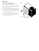
1. Using a draft gauge (inclined manometer) measure t he st atic
pressure of the ret urn duct at the inlet of the unit, (Negative
Pressure).
Supply
Return
Total External Static
2. M easure t he st atic pressure of the supply duct, (Posit ive Pres-
sure).
3. Add the two readings together.
NOTE: Bot h readings may be taken simultaneously and read di-
rectly on the manometer as shown in the illust rat ion above, if so
desired.
4. Consult proper table for quantity of air.
If the external st at ic pressure exceeds the minimum or maximum
allowable st at ics, check for closed dampers, dirt y filters, under-
sized or poorly laid out ductw ork.