
Service Manual


SERVICING
36
S-115 COM PRESSOR BURNOUT
When a compressor burns out, high temperature develops caus-
ing t he refrigerant , oil and mot or insulation to decompose form-
ing acids and sludge.
If a compressor is suspected of being burned-out , att ach a refrig-
erant hose t o the liquid line dill valve and properly remove and
dispose of the refrigerant .
NOTICE
Now det ermine if a burn out has actually occurred. Confirm by
analyzing an oil sample using a Sporlan Acid Test Kit , AK-3 or its
equivalent.
Remove the compressor and obtain an oil sample from the suc-
tion stub. If the oil is not acidic, eit her a burnout has not oc-
curred or the burnout is so mild that a complet e clean-up is not
necessary.
If acid level is unacceptable, t he syst em must be cleaned by us-
ing t he clean-up drier method.
CAUTION
DO NOT ALLOW THE SLUDGE OR OIL TO CONTACT
THE SKIN, SEVERE BURNS MAY RESULT.
NOTE: GOODM AN DOES NOT APPROVE THE FLUSHING M ETHOD
USING R-11 REFRIGERANT.
SUCTION LINE DRIER CLEAN-UP M ETHOD
The POE oils used with R410A refrigerant is an excellent solvent.
In the case of a burnout, the POE oils will remove any burnout
residue left in t he syst em. If not captured by the refrigerant fil-
ter, they will collect in t he compressor or other syst em compo-
nent s, causing a failure of the replacement compressor and/ or
spread contaminants throughout the syst em, damaging additional
components.
Inst all a suction line filter drier. This drier should be inst alled as
close t o the compressor suction fitt ing as possible. The filter must
be accessible and be rechecked for a pressure drop aft er the sys-
tem has operated for a time. It may be necessary t o use new
tubing and form as required.
NOTE: At least twelve (12) inches of the suction line immedi-
ately out of the compressor stub must be discarded due to
burned residue and contaminates.
1. Remove the liquid line drier and expansion valve.
2. Purge all remaining component s wit h dry nitrogen or carbon
dioxide until clean.
3 Inst all new components
including liquid line drier.
4. Braze all joint s, leak t est , evacuate, and recharge system.
5. Start up the unit and record the pressure drop across the
drier.
6. Continue to run the syst em for a minimum of twelve (12)
hours and recheck t he pressure drop across the drier. Pres-
sure drop should not exceed 6 PSIG.
7. Cont inue to run the syst em for several days, repeatedly check-
ing pressure drop across the suction line drier. If the pres-
sure drop never exceeds the 6 PSIG, the drier has trapped
the cont aminants. Remove the suction line drier from the
system.
8. If the pressure drop becomes greater, t hen it must be re-
placed and steps 5 t hrough 9 repeated unt il it does not ex-
ceed 6 PSIG.
NOTICE: Regardless, the cause for burnout must be det ermined
and corrected before t he new compressor is start ed.
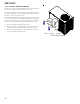
S-122 REVERSING VALVE REPLACEM ENT
Remove the refrigerant charge from the syst em.
When brazing a reversing valve into the system, it is of extreme
import ance that the temperature of the valve does not exceed
250°F. at any time.
Wrap the reversing valve w ith a large rag saturat ed with wat er.
"Re-wet" the rag and thoroughly cool the valve after each braz-
ing operation of the four joints involved. The wet rag around the
reversing valve will eliminate conduction of heat to the valve
body when brazing the line connection.
The use of a w et rag somet imes can be a nuisance. There are
commercial grades of heat absorbing paste that may be substi-
tut ed.
Aft er the valve has been inst alled, leak test, evacuat e and re-
charge.