
Service Manual


SERVICING
30
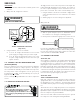
WARNING
DISCONNECT POWER SUPPLY BEFORE SERVICING.
1. Disconnect the heat er lead wires.
2. Using an ohmmeter, check heat er continuity - should test con-
tinuous, if not, replace.
S-18A CHECKING CRANKCASE HEATER THERM OSTAT
Note: Not all models with crankcase heaters will have a
crankcase heater thermostat.
1. Inst all a thermocouple type temperature t est lead on t he dis-
charge line adjacent to the crankcase heater thermost at .
2. Check the temperature at which the control closes its con-
tact s by lowering t he temperature of the control. The crank-
case heater thermostat should close at 67°F ± 5°F.
3. Check the temperature at which the control opens its con-
tact s by raising t he t emperature of the control. The crank-
case heater thermostat should open at 85°F ± 5°F.
4. If not as above, replace control.
S-21 CHECKING REVERSING VALVE AND SOLENOID
Occasionally the reversing valve may st ick in the heat ing or cool-
ing position or in t he mid-position.
When stuck in t he mid-position, part of the discharge gas from
the compressor is direct ed back to the suction side, resulting in
excessively high suction pressure. An increase in the suction line
temperature through the reversing valve can also be measured.
Check operat ion of the valve by st art ing the syst em and switch-
ing t he operat ion from COOLING to HEATING cycle.
If the valve fails to change it s posit ion, test the volt age (24V) at
the valve coil t erminals, while the syst em is on the COOLING cycle.
If no voltage is registered at the coil terminals, check the opera-
tion of the thermost at and the continuity of the connecting wir-
ing from the " O" terminal of the t hermostat to the unit .
If voltage is regist ered at the coil, t ap the valve body lightly while
swit ching t he syst em from HEATING t o COOLING, et c. If this fails
to cause the valve to sw itch positions, remove the coil connec-
tor cap and test the continuity of the reversing valve solenoid
coil. If the coil does not test continuous - replace it.
If the coil t est continuous and 24 volt s is present at the coil t er-
minals, t he valve is inoperat ive - replace it.
S-24 TESTING DEFROST CONTROL
NOTE: PCBDM 133 defrost cont rols have a three (3) minute
compressor off cycle delay.
NOTE: The PCBDM 133 defrost controls are shipped from the fac-
tory wit h the compressor delay option select ed. This will de-ener-
gize t he compressor contactor for 30 seconds on defrost init ia-
tion and defrost termination. If the jumper is set to Normal, the
compressor will continue to run during defrost init iation and
defrost termination. The control will also ignore t he low pres-
sure swit ch connected to R-PS1 and PS2 for 5 minutes upon de-
frost init iation and 5 minutes aft er defrost termination.
To check the defrost cont rol for proper sequencing, proceed as
follows: With power ON; unit not running.
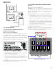
1. Jumper defrost thermostat by placing a jumper wire across
the terminals "DFT" and " R" (" R-DFT" on PCBDM 133) at de-
frost control board.
2. Connect jumper across test pins on defrost control board.
3. Set thermost at to call for heat ing. Syst em should go into de-
frost within 21 seconds.
4. Immediately remove jumper from test pins.
5. Using VOM check for volt age across terminals "C & O" (" O-
RV" on PCBDM 133). M et er should read 24 volt s.
6. Using VOM check for volt age across fan terminals DF1 and
DF2 on the board. You should read line voltage (208-230 VAC)
indicat ing the relay is open in the defrost mode.
7. Using VOM check for volt age across "W2" (W on PCBDM 133)
& "C" terminals on the board. You should read 24 volts.
8. If not as above, replace control board.
9. Set thermost at to off position and disconnect power before
removing any jumpers or wires.
NOTE: Remove jumper across defrost t hermostat before ret urn-
ing syst em to service.
S-25 TESTING DEFROST THERM OSTAT
1. Inst all a thermocouple type temperature test lead on the
tube adjacent to the defrost control. Insulate the lead point
of contact.
2. Check the temperature at which the control closes its con-
tact s by lowering t he temperature of the control. It should
close at approximately 32°F ± 2°F.
3. Check the temperature at which the control opens its con-
tact s by raising t he t emperature of the control. It should open
at approximat ely 60°F.
4. If not as above, replace control.
S-50 CHECKING HEATER LIM IT CONTROL(S)
(OPTIONAL ELECTRIC HEATERS)
Each individual heat er element is prot ected wit h an aut omatic
rest limit cont rol connected in series wit h each element to pre-
vent overheat ing of component s in case of low airflow. This limit
control will open its circuit at approximat ely 150°F. to 160°F and
close at approximately 110°F.