
Service Manual


SERVICING
25
SINGLE PHASE
1. Disconnect the wire leads from the terminal (T) side of the
contactor.
2. With power ON, energize t he contactor.
WARNING
LINE VOLTAGE NOW PRESENT.
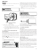
VOLT/OHM
METER
T1
T2
L1L2
CC
Ohmmeter for testing holding coil
Voltmeter for testing contacts
TESTING COM PRESSOR CONTACTOR
(Single Phase)
3. Using a voltmeter, test across terminals.
A. L1 to L2 - No voltage. Check breaker or fuses on main
power supply. If voltage present, proceed to st ep B.
B. T1 t o T2 - M et er should read the same as L1 to L2 in
step A. If voltage readings are not the same as step A,
replace contactor.
S-11 CHECKING LOSS OF CHARGE PROTECTOR
(Heat Pump Models)
The loss of charge protector senses the pressure in the liquid line
and will open its contact s on a drop in pressure. The low pres-
sure control will aut omatically reset itself with a rise in pressure.
The low pressure control is designed to cut-out (open) at ap-
proximat ely 22
+ 7 PSIG. It will aut omat ically cut -in (close) at
approximat ely 50 + 7 PSIG.
Test for continuity using a VOM and if not as above, replace the
control.
S-12 CHECKING HIGH PRESSURE CONTROL
HIGH VOLTAGE!
Disconnect ALL power before servicing
or installing this unit. Multiple power
sources may be present. Failure to do so
may cause property damage, personal injury
or death.
The high pressure cont rol senses the pressure in the liquid line.
If abnormally high discharge pressures develop, the cont acts of
the cont rol open, breaking the control circuit before the com-
pressor motor overloads. This cont rol is automat ically reset.
1. Using an ohmmet er, check across terminals of high pressure
control, with wire removed. If not continuous, the cont acts
are open.
2. Attach a gauge to the access fitting on the liquid line.
With power ON:
WARNING
LINE VOLTAGE NOW PRESENT.
3. St art the syst em and place a piece of cardboard in front of
the condenser coil, raising the condensing pressure.
4. Check pressure at which the high pressure control cut s-out.
If it cuts-out at 610 PSIG ± 10 PSIG, it is operating normally (See
causes for high head pressure in Service Problem Analysis Guide).
If it cuts out below this pressure range, replace the control. The
control should reset at 420 PSIG ± 25 PSIG.
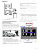
S-15 CHECKING CAPACITOR
CAPACITOR, RUN
A run capacitor is wired across the auxiliary and main windings
of a single phase permanent split capacit or mot or. The capaci-
tors primary function is to reduce the line current while great ly
improving the torque characteristics of a mot or. This is accom-
plished by using the 90° phase relat ionship betw een the capaci-
tor current and voltage in conjunction with the mot or windings
so that the mot or will give two phase operation when connect ed
to a single phase circuit. The capacit or also reduces the line cur-
rent to the mot or by improving the pow er factor.
CAPACITOR, START
SCROLL COM PRESSOR M ODELS
Hard st art components are not required on Scroll compressor
equipped units due to a non-replaceable check valve locat ed in
the discharge line of the compressor. However hard st art kits
are available and may improve low volt age start ing charact eris-
tics.
This check valve closes off high side pressure to the compressor
aft er shut down allowing equalizat ion through the scroll flanks.
Equalization requires only about one or two seconds during which
time the compressor may t urn backw ards.
Your unit comes wit h a 180-second anti-short cycle to prevent
the compressor from st arting and running backwards.