
Service Manual


SERVICING
24
3. Set fan selector switch at thermost at to "ON" posit ion.
4. With volt meter, check for 24 volts at wires C and G.
5. No volt age, indicates t he trouble is in t he t hermostat or wir-
ing.
6. Check the continuity of the t hermostat and wiring. Repair or
replace as necessary.
S-3B COOLING ANTICIPATOR
The cooling anticipator is a small heater (resist or) in the thermo-
stat. During t he " off" cycle it heat s the bimetal element helping
the thermostat call for the next cooling cycle. This prevent s the
room t emperat ure from rising too high before the system is re-
start ed. A properly sized anticipat or should maintain room tem-
perature w ithin 1 1/ 2 to 2 degree range.
The anticipator is supplied in the thermost at and is not to be
replaced. If the ant icipator should fail for any reason, the ther-
most at must be changed.
S-3C HEATING ANTICIPATOR
The heat ing ant icipator is a wire-wound adjust able heater, which
is energized during the "ON" cycle to help prevent overheat ing
of the conditioned space.
The anticipator is a part of the t hermostat and if it should fail for
any reason, t he thermostat must be replaced. See t he following
for recommended heater anticipator set t ing.
To determine the proper sett ing, use an amp meter to measure
the amperage on t he " W" wire going to the t hermostat.
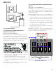
Use an amprobe as show n below. Wrap 10 turns of thermost at
wire around the stationary jaw of the amprobe and divide the
reading by 10.
10 TURNS OF
THERMOSTAT WIRE
(From "W" on thermostat)
STATIONARY JAW
OF AMPROBE
READS 4 AMPS
CURRENT DRAW
WOULD BE .4 AMPS
Checking Heat Anticipator Amp Draw
S-4 CHECKING TRANSFORM ER AND CONTROL
CIRCUIT
A st ep-down transformer (208/ 240 volt primary to 24 volt sec-
ondary) is provided with each package unit. This allows ample
capacit y for use with resist ance heat ers.
WARNING
1. Remove control panel cover or et c. to gain access to trans-
former.
With power ON:
WARNING
LINE VOLTAGE NOW PRESENT.
2. Using a volt met er, check volt age across secondary volt age
side of transformer (R to C).
3. No volt age indicat es faulty transformer, bad wiring, or bad
splices.
4. Check transformer primary voltage at incoming line voltage
connections and/ or splices.
5 If line voltage is present at the primary voltage side of the
transformer and 24 volts is not present on the secondary
side, then the transformer is inoperative. Replace.
S-7 CHECKING CONTACTOR AND/ OR RELAYS
The compressor contactor and other relay holding coils are wired
into the low or line voltage circuits. When the control circuit is
energized t he coil pulls in the normally open cont acts or opens
the normally closed cont acts. When the coil is de-energized,
springs ret urn the contacts to their normal position.
WARNING
DISCONNECT POWER SUPPLY BEFORE SERVICING.
1. Remove the leads from the holding coil.
2. Using an ohmmet er, test across the coil terminals.
If the coil does not test continuous, replace the relay or cont ac-
tor.
S-8 CHECKING CONTACTOR CONTACTS
WARNING
DISCONNECT POWER SUPPLY BEFORE SERVICING.