
Service Manual


SERVICING
23
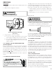
S-1 CHECKING VOLTAGE
WARNING
1. Remove doors, control panel cover, etc. from unit being
test ed.
W ith pow er ON:
WARNING
LINE VOLTAGE NOW PRESENT.
2. Using a volt meter, measure t he volt age across terminals L1
and L2 of the contactor for single phase unit s, and L3, for 3
phase unit s.
3. No reading - indicates open wiring, open fuse(s) no power
or et c. from unit to fused disconnect service. Repair as
needed.
4. With ample volt age at line voltage connectors, energize
the unit .
5. M easure the volt age wit h the unit st arting and operating,
and determine the unit
Locked Rotor Voltage.
Locked Rotor Voltage is the actual voltage available at the
compressor during st arting, locked rotor, or a st alled con-
dition. M easured volt age should be above minimum listed
in chart below.
To measure Locked Rot or Volt age attach a voltmeter to
the run "R" and common "C" terminals of the compressor,
or to the T
1
and T
2
terminals of the contactor. Start the
unit and allow the compressor to run for several seconds,
then shut down the unit. Immediat ely attempt to restart
the unit while measuring the Locked Rot or Volt age.
6. Should read within the voltage tabulation as show n. If t he
volt age falls below the minimum voltage, check the line
wire size. Long runs of undersized wire can cause low volt-
age. If wire size is adequate, notify the local power com-
pany in regards to eit her low or high volt age.
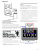
Voltage Min. Max.
460 437 506
208/230 198 253
Unit Supply Voltage
S-2 CHECKING W IRING
WARNING
1. Check wiring visually for signs of overheat ing, damaged in-
sulation and loose connections.
2. Use an ohmmeter to check continuity of any suspected open
wires.
3. If any wires must be replaced, replace with comparable gauge
and insulation thickness.
S-3 CHECKING THERM OSTAT, WIRING, AND
ANTICIPATOR
S-3A THERM OSTAT AND W IRING
WARNING
LINE VOLTAGE NOW PRESENT.
With power ON and t hermostat calling for cooling.
1. Use a voltmeter to verify 24 volts present at thermost at wires
C and R.
2. If no voltage present, check t ransformer and t ransformer
wiring. If 24 volts present, proceed to step 3.
3. Use a voltmeter to check for 24 volts at thermostat wires C
and Y.
4. No volt age indicates t rouble in the t hermostat, wiring or ex-
ternal transformer source.
5. Check the continuity of the t hermostat and wiring. Repair or
replace as necessary.
INDOOR BLOW ER M OTOR
With power ON:
WARNING
LINE VOLTAGE NOW PRESENT.
1. Use a voltmeter to verify 24 volts present at thermost at wires
C and R.
2. If no voltage present, check t ransformer and t ransformer
wiring. If 24 volts present, proceed to step 3.