
Service Manual


SYSTEM OPERATION
17
When the contacts of the room thermost at close, this closes
the circuit from R to Y and R t o G in t he unit.
This energizes the compressor cont actor and will energize the
indoor blower inst antly on models equipped wit h EEM blower
motor.
When the thermostat is sat isfied, it opens its contact s break-
ing t he low voltage circuit causing the compressor contactor
to open and indoor fan to st op aft er the programmed 60 sec-
ond off delay on models equipped with EEM blower mot ors.
If the room thermostat fan selector switch should be set to the
"on" position then the indoor blower would run continuous
rat her than cycling with the compressor.
HEATING CYCLE
COOLING ONLY UNITS
NOTE: The following only applies if the cooling only unit has an
approved electric heat kit inst alled for heat ing. If auxiliary
elect ric heaters should be used, they may be cont rolled by
outdoor thermostats (OT18-60A or OT/ EHR18-60A).
* PC M ODELS EQUIPPED WITH EEM BLOW ER M OTORS
With the thermost at set to the heat position and a call for heat,
R t o W will be energized. This will energize t he electric heat
sequencers and the EEM
motor. The electric heat will be ener-
gized t hrough t he normally open contacts of the electric heat
sequencers. The indoor blower will be energized through W
from the thermost at .
When the thermostat is sat isfied, this breaks the circuit from R
to W. This will t urn off t he electric heaters, and the indoor
blower after the programmed 60 second off delay.
HEAT PUM P UNITS
On a call for first st age heat , t he contact s of the room thermo-
stat close. This energizes terminals R to Y and R to G, the low
volt age circuit to the contactor is completed start ing the com-
pressor and out door fan motor. This also energizes t he indoor
blower instantly on models equipped with EEM blower mo-
tors.
When the thermostat is sat isfied, breaking t he circuit bet w een
R t o Y and R to G, the compressor and out door fan motor will
stop after the programmed 60 second off delay on models
equipped wit h EEM blower motors .
When auxiliary electric heaters are used, a two st age heat ing
single stage cooling thermostat would be installed.
Should the second st age heating contacts in the room thermo-
stat close, which would be wired t o W1 at the unit low voltage
connections, this would energize t he coil(s) of t he electric heat
relay(s). Contact s within the relay(s) w ill close, bringing on the
elect ric resist ance heat ers.
If auxiliary electric heaters should be used, they may be con-
trolled by outdoor thermost at s (OT18-60A or OT/ EHR18-60A).
COOLING
The refrigerant used in the syst em is R-410A. It is a clear, color-
less, non-t oxic and non-irritat ing liquid. R-410A is a 50:50 blend
of R-32 and R-125. The boiling point at atmospheric pressure is
-62.9°F.
A few of the import ant principles that make the refrigerat ion
cycle possible are: heat always flows from a warmer to a cooler
body. Under lower pressure, a refrigerant will absorb heat and
vaporize at a low temperature. The vapors may be drawn off
and condensed at a higher pressure and temperature to be used
again.
The indoor evaporator coil functions to cool and dehumidify
the air condit ioned spaces through the evaporat ive process
taking place within t he coil t ubes.
Heat is continually being t ransferred to the cool fins and tubes
of the indoor evaporator coil by the warm syst em air. This warm-
ing process causes the refrigerant to boil. The heat removed
from the air is carried off by t he vapor.
As the vapor passes through the last tubes of the coil, it be-
comes superheat ed. That is, it absorbs more heat than is nec-
essary to vaporize it . This is assurance that only dry gas will
reach the compressor. Liquid reaching t he compressor can
weaken or break compressor valves.
The compressor increases the pressure of t he gas, t hus adding
more heat, and discharges hot, high pressure superheat ed gas
into the outdoor condenser coil.
In the condenser coil, t he hot refrigerant gas, being warmer
than the outdoor air, first loses it s superheat by heat trans-
ferred from the gas through the t ubes and fins of the coil. The
refrigerant now becomes sat urated, part liquid, part vapor and
then cont inues to give up heat until it condenses to a liquid
alone. Once the vapor is fully liquefied, it continues to give up
heat which subcools the liquid, and it is ready to repeat t he
cycle.
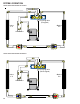
COOLING CYCLE
COOLING ONLY M ODELS
When the contacts of the room thermost at close, making ter-
minals R to Y and R to G, the low voltage circuit to t he contact or
is complet ed st art ing the compressor and outdoor fan mot or.
This also energizes the indoor blower through the 24V signal
from the thermost at .
When the thermostat is sat isfied, breaking t he circuit bet w een
R t o Y and R to G, the compressor and out door fan motor will
stop. The indoor blower will stop after the fan off delay.
If the room thermostat fan selector switch should be set to the
"on" position then the indoor blower would run continuous
rat her than cycling with the compressor.
HEAT PUM P M ODELS
Any time the room thermostat is switched t o cool, t he O ter-
minal is energized. This energizes t he 24 volt coil on the revers-
ing valve and swit ches it to the cooling position.
SYSTEM OPERATION A/ GPC15 & A/ GPH16H41*