
Service Manual


PRODUCT DESIGN
13
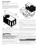
LOCATION & CLEARANCES
NOTE: To ensure proper condensate drainage, unit must be in-
stalled in a level position.
In installations where the unit is installed above ground level
and not serviceable from the ground (Example: Roof Top
installations) the installer must provide a service platform for
the service person with rails or guards in accordance with local
codes or ordinances.
36"
36"
10"
UNIT
WALL
36"
48” MIN.
A/GPC15 & A/GPH16H41**
NOTE: Roof overhang should be no more t han 36" and provisions
made to deflect the warm discharge air out from the overhang.
M inimum clearances are required to avoid air recirculation and
keep the unit operat ing at peak efficiency.
WARNING
TO PREVENT POSSIBLE DAMAGE, THE UNIT SHOULD
REMAIN IN AN UPRIGHT POSITION DURING ALL
RIGGING AND MOVING OPERATIONS. TO FACILITATE
LIFTING AND MOVING IF A CRANE IS USED, PLACE
THE UNIT IN AN ADEQUATE CABLE SLIDE.
Refer to Roof curb Installation Inst ructions for proper curb in-
stallation. Curbing must be inst alled in compliance with the Na-
tional Roofing Contractors Association M anual.
Lower unit carefully onto roof mounting curb. While rigging unit ,
center of gravit y w ill cause condenser end to be lower than sup-
ply air end.
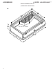
Roof Curb and Platform
A/GPC15 & A/GPH16H41**
* PC15/ * PH16 Package Unit s are designed for outdoor inst alla-
tions only in either resident ial or light commercial applicat ions.
NOTE: To ensure proper condensate drainage, unit must be installed
in a level position.
The connecting ductwork (Supply and Return) can be connected
for horizontal discharge airflow. In t he down discharge applica-
tions, a matching Platform/ Roof Curb (PCCP101-103) and
Downflow Plenum (PCP101-103) is recommended for horizont al
models only.
A ret urn air filter must be inst alled behind the return air grille(s)
or provision must be made for a filter in an accessible location
wit hin the return air duct . The minimum filter area should not
be less than those sizes list ed in the Specification Section. Under
no circumstances should t he unit be operat ed w ithout return air
filters.
A 3/ 4" - 14 NPT drain connector is provided for removal of con-
densat e water from the indoor coil. In order to provide proper
condensate flow , do not reduce t he drain line size.
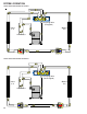
Refrigerant flow control is achieved by use of restrictor orifices.
These models use the FasTest Access Fitting Syst em, with a saddle
that is eit her soldered t o the suction and liquid lines or is fas-
tened with a locking nut to the access fitt ing box (core) and then
screwed int o the saddle.
Do not remove the core from the
saddle until the refrigerant charge has been removed. Failure
to do so could result in property damage or personal injury.
The single phase unit s use permanent split capacitors (PSC) de-
sign compressors. St arting components are therefore not re-
quired. A low M FD run capacitor assists the compressor to st art
and remains in t he circuit during operat ion.
The outdoor fan mot or is a single phase capacitor t ype mot ors.