
User Guide

SERVICING
42
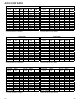
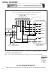
Wiring is subject to change. Always refer to the wiring diagram on the unit for the most up-to-date wiring.
components, causing a failure of the replacement compressor
and/or spread contaminants throughout the system, damag-
ing additional components.
Use AMANA
®
brand part number RF000127 suction line filter
drier kit. This drier should be installed as close to the com-
pressor suction fitting as possible. The filter must be acces-
sible and be rechecked for a pressure drop after the system
has operated for a time. It may be necessary to use new tub-
ing and form as required.
NOTE: At least twelve (12) inches of the suction line immedi-
ately out of the compressor stub must be discarded due to
burned residue and contaminates.
1. Remove compressor discharge line strainer.
2. Remove the liquid line drier and expansion valve.
3 Purge all remaining components with dry nitrogen or car-
bon dioxide until clean.
4. Install new components
including liquid line drier.
5. Braze all joints, leak test, evacuate, and recharge system.
6. Start up the unit and record the pressure drop across the
drier.
7. Continue to run the system for a minimum of twelve (12)
hours and recheck the pressure drop across the drier. Pres-
sure drop should not exceed 6 PSIG.
8. Continue to run the system for several days, repeatedly
checking pressure drop across the suction line drier. If the
pressure drop never exceeds the 6 PSIG, the drier has
trapped the contaminants. Remove the suction line drier
from the system.
9. If the pressure drop becomes greater, then it must be re-
placed and steps 5 through 9 repeated until it does not
exceed 6 PSIG.
NOTICE: Regardless, the cause for burnout must be deter-
mined and corrected before the new compressor is started.
S-122 REVERSING VALVE REPLACEMENT
Remove the refrigerant charge from the system.
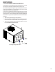
When brazing a reversing valve into the system, it is of ex-
treme importance that the temperature of the valve does not
exceed 250°F. at any time.
Wrap the reversing valve with a large rag saturated with water.
"Re-wet" the rag and thoroughly cool the valve after each braz-
ing operation of the four joints involved. The wet rag around the
reversing valve will eliminate conduction of heat to the valve
body when brazing the line connection.
The use of a wet rag sometimes can be a nuisance. There are
commercial grades of heat absorbing paste that may be sub-
stituted.
After the valve has been installed, leak test, evacuate and re-
charge.
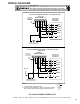
S-200 CHECKING EXTERNAL STATIC
PRESSURE
The minimum and maximum allowable duct static pressure is
found in the Technical Information Manual.
Too great of an external static pressure will result in insuffi-
cient air that can cause icing of the coil, whereas too much air
can cause poor humidity control, and condensate to be pulled
off the evaporator coil causing condensate leakage. Too much
air can cause motor overloading and in many cases this con-
stitutes a poorly designed system. To determine proper air
movement, proceed as follows:
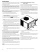
1. Using a draft gauge (inclined manometer) measure the static
pressure of the return duct at the inlet of the unit, (Negative
Pressure).
Total External Static
2. Measure the static pressure of the supply duct, (Positive
Pressure).
3. Add the two readings together.
NOTE: Both readings may be taken simultaneously and read
directly on the manometer as shown in the illustration above, if
so desired.
4. Consult proper table for quantity of air.
If the external static pressure exceeds the minimum or maxi-
mum allowable statics, check for closed dampers, dirty filters,
undersized or poorly laid out ductwork.