TECHNICAL MANU AL MANUAL GDS8 & GHS8 33-3/8" 80% Gas Furnace Units • Refer to Service Manual RS6612006 for troubleshooting information. • Refer to the appropriate Parts Catalog for part number information. • Model numbers listed on page 3. This manual is to be used by qualified, professionally trained HVAC technicians only. Goodman does not assume any responsibility for property damage or personal injury due to improper service procedures or services performed by an unqualified person.
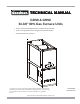
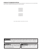
PRODUCT IDENTIFICATION The model and manufacturing number are used for positive identification of component parts used in manufacturing. Please use these numbers when requesting service or parts information.
PRODUCT IDENTIFICATION The model and manufacturing number are used for positive identification of component parts used in manufacturing. Please use these numbers when requesting service or parts information.
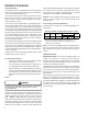
PRODUCT DESIGN General Operation The G*S8 furnaces are equipped with an electronic ignition device used to light the burners and an induced draft blower to exhaust combustion products. An interlock switch prevents furnace operation if the inner blower door is not in place. Keep the blower access door in place except for inspection and maintenance. (See illustration on pages 5 and 6.) This furnace is also equipped with a self-diagnosing electronic control module.
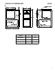
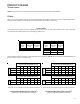
PRODUCT DIMENSIONS GHS8 MODEL A B GHS80403A*** 14 1/2" 12 1/2" GHS80604B*** 17 1/2" 16" GHS80805C*** 21" 19 1/2" 5
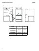
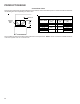
PRODUCT DESIGN GDS8 A 28” B High Voltage Electrical Lov Voltage Electrical 33-3/8” Gas Inlet MODEL A B 14 1/2" 12 1/2" GDS80804B*** 17 1/2" 16" GDS81005C*** 21" 19 1/2" GDS80403A*** GDS80603A*** 6
PRODUCT DESIGN GHS8***B* PRESSURE SWITCH TRIP POINTS AND USAGE CHART Model Trip Point ID Blower Pressure Switch ID Blower Pressure Switch Part # GHS80403A*B * -0.70 B1370158 GHS80604B*B* -0.80 0130F00042 GHS80805C*B* -0.75 B1370179 For installations in Canada, the GHS furances are certified only to 4,500 ft. * Negative pressure readings are in inches of water column (*w.c.
PRODUCT DESIGN GDS8***B* PRESSURE SWITCHES Model Part No. Opens* GDS80403A*B* B1370142 -0.60 GDS80603A*B* B1370142 -0.60 GDS80804B*B* B1370142 -0.60 GDS81005C*B* 0130F00042 -0.
PRODUCT DESIGN Thermostats: NOTE: Complete lineup of thermostats can be found in the Thermostat Specification Sheets. Filters: Filters are required with this furnace and must be provided by the installer. The filters used must comply with UL900 or CAN/ULCS111 standards. Installing this furnace without filters will void the unit warranty Upflow Filters This furnace has provisions for the installation of return air filters at the side and/or bottom return.
PRODUCT DESIGN Counterflow Filters This furnace has provisions for the installation of return air filters at the counterflow top return. The furnace will accommodate the following filter sizes depending on cabinet size: Counterflow Top Return Return Air Optional Access Door Cabinet Width "A" Min 21 24 1/2 21 24 1/2 21 24 1/2 Filter Area Qty Filter Size Dimension "A" (in) (in) (in2) 600 2 15 X 20 X 1 800 2 20 X 20 X 1 1000 2 25 X 20 X 1 13.0 11.3 18.8 17.7 24.3 23.
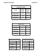
FURNACE SPECIFICATIONS MODEL GDS8***B* GDS80403A*B* GDS80603A*B* GDS80804B*B* GDS81005C*B* 40,000 60,000 80,000 100,000 32,000 48,000 64,000 80,000 80% 80% 80% 80% .20 - .50 .20 - .50 .20 - .50 .20 - .50 Temperature Rise (°F) 25-55 30-60 35-65 40 - 70 Pressure Switch Trip Point (" w.c.) -0.60 -0.60 -0.60 -0.8 0 10 X 6 10 x 6 10 x 8 10 x 10 1/3 1/3 1/2 3/4 Btuh Input (US) High Fire Output (US) High Fire ( 1) A.F.U.E. Rated External Static (" w.c.
FURNACE SPECIFICATIONS MODEL GHS8***B* GHS80403A*B* GHS80604B*B* GHS80805C*B* Input, Natural Gas (BTUH) 40,000 60,000 80,000 Output, Natural Gas (BTUH) 32,000 48,000 64,000 Output, LP (BTUH) 32,000 48,000 64,000 (1) 80.0% 80.0% 80.0% 0.20 - 0.50 0.20 - 0.50 0.20 - 0.50 Temperature Rise (°F) 20-50 20-50 35 - 65 Pressure Switch T rip Point (" w.c.) -0.70 -0.80 -0.75 11” x 6” 11” x 8” 11” x 10” 1/2 3/4 3/4 A.F.U.E. Rated External Static (" w.c.
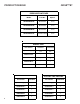
BLOWER PERFORMANCE SPECIFICATIONS GHS8***B* (CFM & Temperature Rise vs. External Static Pressu re) Model Motor Speed Tons AC at 0.5" ESP GHS80403A*B* GHS80604B*B* GHS80805 C*B* EXTERNAL STAT IC PRESSURE (Inches Water Column) 0.1 0.2 0.3 0.4 0.5 0.6 0.7 0.8 CFM RISE CFM RISE CFM RISE CFM RISE CFM RISE CFM RISE CFM RISE CFM RISE HIGH 3.0 1 739 ---- 1656 ---- 1601 ---- 1551 ---- 1513 20 1460 22.8 1413 23.6 1353 24.6 MED 2.
BLOWER PERFORMANCE SPECIFICATIONS GDS8***B* (CFM & Temperature Rise vs. External Static Pressure) Model Motor Speed Tons AC at 0.5" ESP GDS8 0403A*B* GDS8 0603A*B* GDS8 0804B*B* GDS81005C*B* EXTERNAL STATIC PRESSURE (Inches Water Column) 0.1 0.2 0.3 0.4 0.6 0.5 0.7 0.8 CFM RISE CFM RISE CFM RISE CFM RISE CFM RISE CFM CFM CFM HIGH 3.0 1 353 ---- 1290 --- - 1246 ---- 1199 25 1149 26 1116 1 116 1099 MED 2.
TEMPERATURE RISE 10 20 30 40 50 60 70 30 80 90 100 40 50 60 700 600 CFM 90 100 2000 2200 2400 CFM 1800 1600 1400 OUTPUT BTU/HR x 1000 80 1200 1100 1000 900 70 800 FORMULAS 110 120 130 140 BTU OUTPUT = CFM x 1.08 x RISE BTU OUTPUT RISE = ÷ CFM 1.
WIRING DIAGRAMS G*S8 HIGH VOLTAGE! DISCONNECT ALL POWER BEFORE SERVICING OR INSTALLING THIS UNIT. MULTIPLE POWER SOURCES MAY BE PRESENT. FAILURE TO DO SO MAY CAUSE PROPERTY DAMAGE, PERSONAL INJURY OR DEATH. WA RNING :D ISC ONN ECT P OW ER BEFORE SE RV ICIN G.WIR ING TO UN IT MUS T BE PR OP ER LY POLAR IZED A ND G RO UND ED.