
GDS8 Installation Manual

26
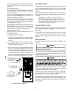
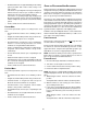
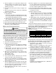
White-Rodgers Model 36J22
Gas Valve On/Off
Selector Switch
Inlet
Pressure
Tap
Pressure Regulator
(under cap screw)
Outlet
Pressure
Tap
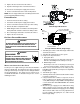
Honeywell Model VR8215 (Single-Stage)
1. Turn OFF gas to furnace at the manual gas shutoff valve
external to the furnace.
2. Turn OFF all electrical power to the system.
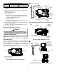
3. Inlet pressure tap connections:
a. Honeywell Valve:
Remove the inlet pressure Tap plug. Install an 1/8”
NPT hose barb fitting into the outlet pressure tap.
b. White-Rodgers valve:
Back inlet pressure test screw (inlet pressure Tap out
one turn (counterclockwise, not more than one turn).
4. Attach a hose and manometer to the outlet pressure
barb fitting (Honeywell valve) or inlet pressure Tap White-
Rodgers valve).
5. Turn ON the gas supply.
6. Turn On power and close thermostat “R” and “W” contacts
to provide a call for heat.
7. Using a leak detection solution or soap suds, check for
leaks at outlet pressure Tap plug (Honeywell valve) or
screw (White-Rodgers valve). Bubbles forming indicate
a leak. SHUT OFF GAS AND REPAIR ALL LEAKS
IMMEDIATELY!
8. Measure the gas supply pressure with burners firing.
Adjust supply pressure using the Inlet Gas Supply
Pressure table shown below. If supply pressure reading
differs from the table, make necessary adjustments to
pressure regulator, gas piping size, etc., and/or consult
with local gas utility.
8. Replace the door on the front of the furnace.
9. Open the manual gas valve external to the furnace.
10. Turn on the electrical power supply to the furnace.
11. Set the room thermostat to the desired temperature.
NOTE: There is an approximate 30 second delay between ther-
mostat energizing and burner firing.
FURNACE S HUTDOWN
1. Set the thermostat to lowest setting.
2. Turn off the electrical power supply to the furnace.
3. Set the room thermostat to the lowest possible setting.
4. Remove the burner compartment door.
5. White-Rodgers valve: Push switch to the OFF position.
Honeywell valve: Slide the switch to the OFF position.
6. Close manual gas shutoff valve external to the furnace.
7. Replace the door on the unit.
GAS SUPPLY PRESSURE MEASUREMENT
CAUTION
T
O
PREVENT
UNRELIABLE
OPERATION
OR
EQUIPMENT
DAMAGE
,
THE
INLET
GAS
SUPPLY
PRESSURE
MUST
BE
AS
SPECIFIED
ON
THE
UNIT
RATING
PLATE
WITH
ALL
OTHER
HOUSEHOLD
GAS
FIRED
APPLIANCES
OPERATING
.
HIGH VOLTAGE !
D
ISCONNECT
ALL
POWER
BEFORE
SERVICING
OR
INSTALLING
THIS
UNIT
. M
ULTIPLE
POWER
SOURCES
MAY
BE
PRESENT
. F
AILURE
TO
DO
SO
MAY
CAUSE
PROPERTY
DAMAGE
,
PERSONAL
INJURY
OR
DEATH
.
WARNING
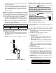
MODELS USING SINGLE STAGE GAS VALVES
The line pressure supplied to the gas valve must be within the
range specified below. The supply pressure can be measured
at the gas valve inlet pressure tap or at a hose fitting installed in
the gas piping drip leg. The supply pressure must be mea-
sured with the unit OFF. To measure inlet pressure, use the
following procedure.