
GDS8 Installation Manual

18
To ensure proper unit grounding, the ground wire should run
from the furnace ground screw located inside the furnace junc-
tion box all the way back to the electrical panel. NOTE: Do
not use gas piping as an electrical ground. To confirm proper
unit grounding, turn off the electrical power and perform the
following check.
1. Measure resistance between the neutral (white)
connection and one of the burners.
2. Resistance should measure 10 ohms or less.
This furnace is equipped with a blower door interlock switch
which interrupts unit voltage when the blower door is opened for
servicing. Do not defeat this switch.
24 VOLT THERMOSTAT W IRING
NOTE: Wire routing must not interfere with circulator blower
operation, filter removal, or routine maintenance.
Low voltage connections can be made through either the right
or left side panel. Thermostat wiring entrance holes are located
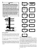
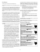
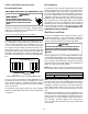
in the blower compartment. The following figure shows con-
nections for a “heat only” system and “heat/cool system”.
Furnace
Control
Furnace
Control
Remote
Condensing
Unit
Heating
Room
Thermostat
Heating/Cooling
Room Thermostat
WW
Typical Field Wiring (24 VAC Control Circuit)
This furnace is equipped with a 40 VA transformer to facilitate
use with most cooling equipment. Consult the wiring diagram,
located on the blower compartment door, for further details of
115 Volt and 24 Volt wiring.
A single-stage thermostat with only one heating stage can be
used to control this furnace.
GME8 & AMEH8 FURNACES WITH 2-STAGE CONDENSER
FIELD W IRING
The GME8 and AMEH8 model furnaces may be used with
a 2-stage outdoor air conditioner. A two stage cooling/single
stage gas heat thermostat is required, in addition to a field
supplied relay. The relay must have a 24VAC coil and
contacts rated for up to 1 horse power at 125VAC.
1. Install the field supplied relay on the control mount-
ing panel near the furnace ignition control. The relay
should be installed such that the motor leads will
reach the relay contact terminals.
2. Connect the “Y2” (high stage cool) thermostat
terminal to one coil terminal of the field supplied
relay. Connect the other field supplied relay coil
terminal to the “C” terminal on the furnace ignition
control. Typical 18AWG thermostat wire may be
used.
3. Connect the common terminal of the field supplied
relay to the “LINE-H” terminal on the furnace ignition
control. Use wiring having copper conductors only
and a temperature rating of at least 105°C.
4. Using the GME8 airflow tables in this manual,
determine the motor speed tap needed to deliver the
required high stage cooling airflow. Connect the
selected motor speed tap to the normally open
terminal on the field supplied relay. Use wiring
having copper conductors only and a temperature
rating of at least 105°C.
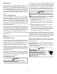
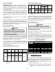
5. See the wiring schematic below.
Furnace
Control
Remote Condensing Unit
Heating/Cooling
Room Thermostat
Y
Y1
Y
1
Y
2
Lo-Heat
Hi-Heat
Cool
Line-H
T4
T2
T3
T5
ECO-TECH
MOTOR
Field
Supplied
Relay
Y
2
Field Wiring for GME8 & AMEH8 Furnaces
with 2-Stage Condenser
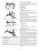
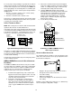
SETTING THE HEAT A NTICIPATOR
The following method should be used in measuring the amp
draw of the control circuit to assure proper adjustment of the
thermostat heat anticipator
• Wrap the “R” leg around a clip-on ammeter 10 times.
• Energize the furnace in the heat mode.
• Record the reading.
• Divide this reading by 10.
• Set the heat anticipator on the thermostat to match
this reading.
Example: If the reading on the ammeter is “4”, divide this by
10. The anticipator setting will be .4 amps.