
GCVM96 & GMVM96 Technical Information

5
PRODUCT DESIGN
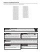
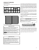
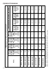
High Altitude Derate
Altitude certification of the *CVM96 and *MVM96 furnaces
is up to 10,000 ft.
High
Stage
Low
Stage
Natural None
#45
1
3.5" w.c. 1" w.c. None
Propane LPKMOD***** 1.25MM
2
10.0"
w.c.
2.6" w.c. None
Manifold Pressure
Pressure
Switch
Change
Altitude Kit
NOTE: In Canada, gas furnaces are only certified to 4500 feet.
Orifice
2
Except 115,000 BTU: #55
1
Except 115,000 BTU: #43
Gas
0-10,000
GCVM961005DX LPKMOD100CF
A/GCVM960604CX LPKMOD060CF
A/GCVM960805DX LPKMOD080CF
A/GMVM961005DX
A/GMVM961155DX
LPKMOD060UF
LPKMOD080UF
LPKMOD100UF
LPKMOD115UF
Furnace Model LP Kit
A/GMVM960603BX
A/GMVM960805CX
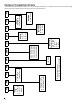
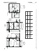
24 VOLT T HERMOSTAT W IRING
W
IRE
ROUTING
MUST
NO T
INTER FER E
WITH
CIRCULATOR
BLOWER
OPERATION
,
FILTER
REM OVAL
OR
RO U TIN E
MAINTENANCE
.
A
REMOVABLE
PLUG
CO NNECTOR
IS
PROVIDED
WITH
THE
CONTROL
TO
MAKE
THERMOSTAT
WIRE
CONNECTIONS
.T
HIS
PLUG
MAY
BE
REMOVED
,
WIRE
CONNECTIONS
MADE
TO
THE
PLUG
,
AND
REPLACE D
.I
T
IS
RECO MMENDED
THAT
MULT IPLE
WIRES
INTO
A
SINGLE
TERMIN AL
BE
TWISTED
TOGETHE R
PRIO R
TO
INSERTING
INTO
THE
PLUG
CONNECTOR
.F
AILURE
TO
DO
SO
MAY
RESULT
IN
INTERM ITTENT
OPERATION
.
STRONGLY
IMPORTANT NOTE
D
IP
SWITCH
#13MUST
BE
SET
TO
MATCH
THERMOSTAT
TYPE
.T
OSE
THE
CTK01AA
COMMUNICATING
THERMOSTAT
,
DIP
SWITCH
#13
MUST
BE
SET
TO
ON
POSITION
.T
HIS
IS
ALSO
THE
CORRECT
SETTING
FOR
A
NON
‐
COMMUNICATING
2‐
STAGE
THERMOSTAT
.T
O
USE
CTK02AA
MODULATING
THERMOSTAT
,
CHECK
TO
MAKE
SURE
DIP
SWITCH
#13
IS
IN
THE
OFF
POSITION
(
FACTORY
POSITION
).T
HIS
IS
ALSO
THE
CORRECT
POSITION
WHEN
USING
A
NON
‐
COMMUNICATING
SINGLE
‐
STA G E
THERMOSTAT
.
U
IMPORTANT NOTE
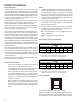
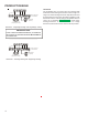
As a two-stage non-communicating furnace, the furnace inte-
grated control module provides terminals for both “W1” and “W2”,
and “Y1” and “Y2” thermostat connections. This allows the fur-
nace to support the following system applications: ‘Two-Stage
Heating Only’, ‘Two-Stage Heating with Single Stage Cooling’,
and ‘Two-Stage Heating with Two-Stage Cooling’. Refer to the
following figures for proper connections to the integrated control
module.
Low voltage connections can be made through either the right or
left side panel. Thermostat wiring entrance holes are located in
the blower compartment. The following figure shows connec-
tions for a “heat/cool system”.
This furnace is equipped with a 40 VA transformer to facilitate
use with most cooling equipment. Consult the wiring diagram,
located on the blower compartment door, for further details of
115 Volt and 24 Volt wiring.
NOTE: Use of ramping profiles requires a jumper between
Y1 and O.
T
HERM OSTAT
“R”
REQUIRE D
IF
OUTDOOR
UNIT
IS
EQU IPPE D
WITH
A
C
OMFORT
A
LERT
™
MODULE
OR
IF
THE
OUTDOOR
UNIT
IS
A
PART
OF
THE
C
OMFORT
N
ET
™
FAMILY
OF
EQU IP M EN T
.
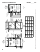
IMPORTANT NOTE
AUX
DEHUM
W2
C
1
Y1
2
R
W1
Y2
G
O
24 V THERMOSTAT CONNECTIONS
Low Voltage Connections with Auxiliary Terminals
The auxiliary contacts are shipped with a factory installed
jumper. As an option, the auxiliary contacts may be wired
to a normally closed float switch. In the event of open
contacts, the furnace will be disabled until the condition is
corrected. These are 24 volt terminals fed internally, do not
apply another voltage source to these terminals.