
GCVM96 & GMVM96 Technical Information

14
PRODUCT DESIGN
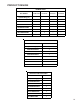
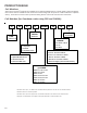
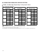
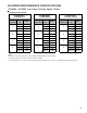
Counterflow Filters
"A"
Min
Return Air
Optional
Access
Door
Return air filters may be installated at the at the counterflow top return. A field supplied center filter support must be provided
by the installer in order to use the top return. The furnace will accommodate the following counterflow top return filter sizes
depending on cabinet size:
Refer to Minimum Filter Area tables to determine filter area requirement. NOTE: Filters can also be installed elsewhere
in the duct system such as a central return.
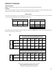
Cabinet Width
Filter Area
(in
2
)
Qty
Filter Size
(in)
Dimension "A"
(in)
17 1/2 14.2
21 13.0
24 1/2 11.3
17 1/2 19.7
21 18.8
24 1/2 17.7
17 1/2 25.0
21 24.3
24 1/2 23.4
800 2 20 X 20 X 1
1000 2 25 X 20 X 1
Counterflow Top Return
600 2 15 X 20 X 1
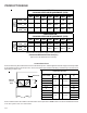
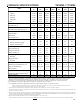
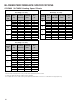
Permanent Minimum Filter Area (in
2
)
[Based on a 600 ft/min filter face velocity]
*Minimum filter area dictated by heating airflow requirement.
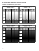
600 800 1000 1200 1400 1600 2000
0603__XA --- --- 627* 627* 672 768 ---
0805__XA --- --- --- 836* 836* 836* 960
1005__XA
1155__XA
--- --- --- 940* 940* 940* 960
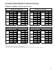
600 800 1000 1200 1400 1600 2000
0604__XA --- --- 320* 320* 336 384 ---
0805__XA
1005__XA
--- --- --- 427* 427* 427* 480
Input
Airflow
UPFLOW
COOLING AIRFLOW REQUIREMENT (CFM)
COUNTERFLOW
COOLING AIRFLOW REQUIREMENT (CFM)
Input
Airflow