
GCVM96 & GMVM96 Installation Instructions

42
may require specific quantity of air, consult installation instruc-
tions of those devices for requirements.
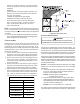
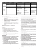
3. Knowing the furnace model, locate the high stage cooling
air flow table. Look up the cooling air flow determined in
step 2 and find the required cooling speed and adjustment
setting.
Example: A *MVM960603BX furnace installed with a
2.5 ton air conditioning system. The air flow
needed is 1000 CFM. Looking at the cooling
speed chart for *MVM960603BX, find the air
flow closest to 1000 CFM. A cooling airflow
of 1000 CFM can be attained by selecting
the cooling speed “C” and the adjustment
to “normal”.
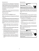
Model Tap
Low
Stage
Cool
High
Stage
Cool
100%
Heat
*CFM
A 370 660 1220
B 540 860 1340
C 790 1150 1460
D 980 1470 1590
A 530 900 1600
B 730 1100 1710
C 930 1430 1800
D 1220 1880 1910
A 500 780 1730
B 740 1070 1770
C 920 1380 1840
D 1160 1780 1870
A 390 630 950
B 550 800 1050
C 680 1000 1170
D 800 1210 1270
A 540 830 1600
B 750 1090 1690
C 980 1460 1800
D 1210 1800 1890
A 510 790 1810
B 710 1100 1850
C 910 1410 1890
D 1160 1830 1940
A 510 790 1810
B 710 1100 1850
C 910 1410 1890
D 1160 1830 1940
*MVM961155DX*
*100% CFM shown. CFM will vary proportionally with the gas valve
BTU/H input.
*CVM960805DX*
*CVM960604CX*
*MVM961005DX*
*MVM960805CX*
*MVM960603BX*
*CVM961005DX*
4. Continuous fan speed is selectable at 25%, 50%, 75%
or 100% of the furnace’s maximum airflow capability.
Example: If the furnace’s maximum airflow capability is
2000 CFM, the continuous fan speed at 25%
will be 0.25 x 2000 or 500 CFM.
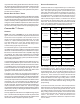
5. Locate the blower speed selection DIP switches on the
integrated control module. Select the desired “cooling”
speed tap by positioning switches 1 and 2 appropriately.
Select the desired “adjust” tap by positioning switches 9
and 10 appropriately. Refer to the DIP switch chart for
switch positions and their corresponding taps. Verify CFM
by noting the number displayed on the dual 7-segment
LED display.
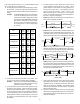
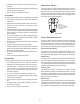
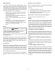
6. The multi-speed circulator blower also offers several
custom ON/OFF ramping profiles for cooling. These
profiles may be used to enhance cooling performance
and increase comfort level. The ramping profiles are
selected using DIP switches 7 and 8. Refer to the
bullet points below for a description of each ramping
profile. Verify CFM by noting the number displayed on
the dual 7-segment LED display.
• Profile A provides only an OFF delay of one (1) minute at
100% of the cooling demand airflow.
OFF
100% CFM 100% CFM
1 min
OFF
• Profile B ramps up to full cooling demand airflow by first
stepping up to 50% of the full demand for 30 seconds. The
motor then ramps to 100% of the required airflow. A one (1)
minute OFF delay at 100% of the cooling airflow is provided.
50% CFM
1/2 min
100% CFM
100% CFM
1 min
OFF
OFF
• Profile C ramps up to 85% of the full cooling demand
airflow and operates there for approximately 7 1/2 minutes.
The motor then steps up to the full demand airflow. Profile
C also has a one (1) minute 100% OFF delay.
100% CFM
OFF
OFF
• Profile D ramps up to 50% of the demand for 1/2 minute,
then ramps to 85% of the full cooling demand airflow and
operates there for approximately 7 1/2 minutes. The motor
then steps up to the full demand airflow. Profile D has a 1/
2 minute at 50% airflow OFF delay.
OFF
OFF
Airflow Table
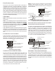
7. Select the heating speed for your model from the heating
speed table in this manual. The “adjust” setting (already
established by the cooling speed selection) determines
which set of speeds are available. The selected speed
must provide a temperature rise within the rise range listed
with the particular model.
8. Select the desired “heating” speed tap by positioning
switches 3 and 4 appropriately. Refer to the airflow table.
Verify CFM by noting the number displayed on the dual 7-
segment LED display.