
GCVM96 & GMVM96 Installation Instructions

39
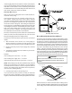
4. Remove the burner compartment door.
NOTE: This furnace is equipped with an ignition device which
automatically lights the burner. Do not try to light the burner by
hand.
5. Move the furnace gas valve manual control to the OFF
position.
6. Wait five minutes then smell for gas. Be sure to check
near the floor as propane is heavier than air.
7. If you smell gas after five minutes, immediately follow the
Safety Considerations on page 4 of this manual. If you do
not smell gas after five minutes, move the furnace gas
valve manual control to the ON position.
8. Replace the burner compartment door.
9. Open the manual gas shutoff valve external to the furnace.
10. Turn on the electrical power to the furnace.
11. Adjust the thermostat to a setting above room temperature.
12. After the burners are lit, set the thermostat to desired
temperature.
FURNACE SHUTDOWN
1. Set the thermostat to the lowest setting.
The integrated control will close the gas valve and extinguish
flame. Following a 15 second delay, the induced draft blower
will be de-energized. After a 120, 150, 180 or 210-second
delay period (field selectable delay OFF [90, 120, 150, 180]
plus 30-second ramp down), the circulator blower de-
energizes.
2. Remove the burner compartment door and move the furnace
gas valve manual control to the OFF position.
3. Close the manual gas shutoff valve external to the furnace.
4. Replace the burner compartment door.
GAS SUPPLY PRESSURE MEASUREMENT
CAUTION
T
O
PREVEN T
UNRELIABLE
OPERATION
OR
EQU IP MENT
DAM AGE
,
THE
INLET
GAS
SUPPLY
PRESSURE
MUST
BE
AS
SP ECIF IED
ON
THE
UNIT
RATING
PLATE
WITH
ALL
OTHER
HOUSEHOLD
GAS
FIRED
APPLIANCES
OPERATING
.
The line pressure supplied to the gas valve must be within the
range specified in the Inlet Gas Supply Pressure table. The sup-
ply pressure can be measured at the gas valve inlet pressure tap
or at a hose fitting installed in the gas piping drip leg. The supply
pressure must be measured with the burners operating. To mea-
sure the gas supply pressure, use the following procedure:
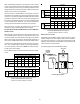
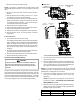
A
TMOSPHERE
PORT
DIRECTION
FLOW
PRESSURE
SWITCH
CONNECTION
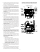
Honeywell Model VR9205R
Outlet
Pressure
Tap
1/8 NPT
Inlet
Pressure
Tap
1/8 NPT
2-PIN
POWER
CONNECTOR
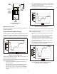
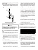
i
M
a
n
o
m
e
t
e
r
M
a
n
o
m
e
t
e
r
H
o
s
e
O
p
e
n
t
o
A
t
m
o
s
p
h
e
r
e
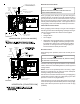
Honeywell Model VR9205R Connected to Manometer
1. Turn OFF gas to furnace at the manual gas shutoff valve
external to the furnace.
2. Connect a calibrated water manometer (or appropriate gas
pressure gauge) at either the gas valve inlet pressure tap
or the gas piping drip leg. See Honeywell VR9205R gas
valve figure for location of inlet pressure tap.
NOTE: If measuring gas pressure at the drip leg or Honeywell
VR9205R gas valve, a field-supplied hose barb fitting must be
installed prior to making the hose connection.
3. Turn ON the gas supply and operate the furnace and all
other gas consuming appliances on the same gas
supply line.
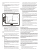
NOTE: To bring furnace up to High Fire, see instructions
for field test mode in GAS MANIFOLD PRESSURE
MEASUREMENT section.
4. Measure furnace gas supply pressure with burners firing.
Supply pressure must be within the range specified in the
Inlet Gas Supply Pressure table.
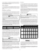
Natural Gas Minimum: 4.5" w.c. Maximum: 10.0" w.c.
Propane Gas Minimum: 11.0" w.c. Maximum: 13.0" w.c.
Inlet Gas Supply Pressure