
GCVM96 & GMVM96 Installation Instructions

34
PROPANE GAS TANKS AND PIPING
I
F
THE
GAS
FURNACE
IS
INSTALLED
IN
A
BASEMENT
,
AN
EXC AVATED
AREA
OR
CONFI NED
SPACE
,
IT
IS
STRONGLY
RE COMMENDED
TO
CONTA CT
A
PROPANE
SUPPLIER
TO
INSTA LL
A
GAS
DETECTING
WARNING
DEVICE
IN
CASE
OF
A
GAS
LEA K
.
S
INC E
PROPA NE
GAS
IS
HEAVIER
THAN
AIR
,
ANY
LEA KING
GAS
CAN
SETTLE
IN
ANY
LOW
AREAS
OR
CONFI NED
SPACE S
.
P
ROPANE
GAS
ODORANT
MAY
FADE
,
MAKING
THE
GAS
UNDETECTABLE
EXCEPT
WITH
A
WARNING
DEVICE
.
•
•
WARNING
A gas detecting warning system is the only reliable way to detect a
propane gas leak. Rust can reduce the level of odorant in pro-
pane gas. Do not rely on your sense of smell. Contact a local
propane gas supplier about installing a gas detecting warning sys-
tem. If the presence of gas is suspected, follow the instructions
listed in the Safety Precautions section of this manual.
All propane gas equipment must conform to the safety standards
of the National Board of Fire Underwriters, NBFU Manual 58.
CANADA: National Standard of Canada, Natural Gas and Pro-
pane Installation Code (NSCNGPIC) CSA B149.1—2010.
For satisfactory operation, propane gas pressure must be 10” WC
+ .5” WC at the furnace manifold with all gas appliances in opera-
tion. Maintaining proper gas pressure depends on three main fac-
tors:
1. Vaporization rate, depending on temperature of the liquid,
and “wetted surface” area of the container or containers.
2. Proper pressure regulation. (Two-stage regulation is
recommended for both cost and efficiency).
3. Pressure drop in lines between regulators, and between
second stage regulator and the appliance. Pipe size will
depend on length of pipe run and total load of all appliances.
Complete information regarding tank sizing for vaporization, rec-
ommended regulator settings, and pipe sizing is available from
most regulator manufacturers and propane gas suppliers.
Since propane gas will quickly dissolve white lead and most stan-
dard commercial compounds, special pipe dope must be used.
Pipe dope used on propane gas installations must be approved
for use with propane gas.
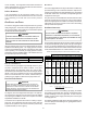
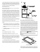
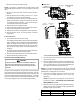
Refer to the following illustration for typical propane gas installa-
tions and piping.
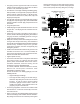
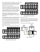
200 PSIG
Maximum
5 to 15 PSIG
(20 PSIG Max.)
Continuous
11" W.C.
Second Stage
Regulator
First Stage
Regulator
Propane Gas Installation (Typ.)
3/8" 1/2" 5/8" 3/4" 7/8" 1/2" 3/4"
10 730 1,700 3,200 5,300 8,300 3,200 7,500
20 500 1,100 220 3,700 5,800 2,200 4,200
30 400 920 2,000 2,900 4,700 1,800 4,000
40 370 850 1,700 2,700 4,100 1,600 3,700
50 330 770 1,500 2,400 3,700 1,500 3,400
60 300 700 1,300 2,200 3,300 1,300 3,100
80 260 610 1,200 1,900 2,900 1,200 2,600
100 220 540 1,000 1,700 2,600 1,000 2,300
125 200 490 900 1,400 2,300 900 2,100
150 190 430 830 1,300 2,100 830 1,900
175 170 400 780 1,200 1,900 770 1,700
200 160 380 730 1,100 1,800 720 1,500
Pipe or
Tubing
Length
Feet
Tubing Size, O.D. Type L
Nominal Pipe Size
Schedule 40
Sizing Between First and Second Stage Regulator*
Maximum Propane Capacities listed are based on 2 psig pressure drop at 10 psig setting.
Capacities in 1,000 BTU/hour.
To convert to capacities at 15 psig settings - multiply by 1.130
To convert to capacities at 5 psig settings - multiply by 0.879
Propane Gas Piping Chart I
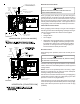
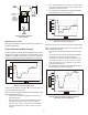
3/8" 1/2" 5/8" 3/4" 7/8" 1/2" 3/4" 1" 1-1/4" 1-1/2"
10 39 92 199 329 501 275 567 1,071 2,205 3,307
20 26 62 131 216 346 189 393 732 1,496 2,299
30 21 50 107 181 277 152 315 590 1,212 1,858
40 19 41 90 145 233 129 267 504 1,039 1,559
50 18 37 79 131 198 114 237 448 913 1,417
60 16 35 72 1,211 187 103 217 409 834 1,275
80 13 29 62 104 155 89 185 346 724 1,066
100 11 26 55 90 138 78 162 307 630 976
125 10 24 48 81 122 69 146 275 567 866
150 9 21 43 72 109 63 132 252 511 787
200 8 19 39 66 100 54 112 209 439 665
250 8 17 36 60 93 48 100 185 390 590
Tubing Size, O.D. Type L
Nominal Pipe Size
Schedule 40
Pipe or
Tubing
Length
Feet
*Data in accordance with NFPA pamphlet No. 54
Sizing Between Second or Second Stage Regulator & Appliance*
Maximum Propane Capacities listed are based on 1/2" W.C. pressure drop at 11" W.C. setting.
Capacities in 1,000 BTU/hour.
Propane Gas Piping Chart II
C
IRCULATING
A
IR
& F
ILTERS
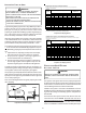
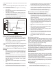
DUCT WORK - AIR FLOW
N
EVER
ALLO W
THE
PRODUCTS
OF
CO MBUSTIO N
,
INC LUDIN G
CARBON
MONOXIDE
,
TO
ENTER
THE
RETURN
DUCT
WORK
OR
CIRCULATION
AIR
SUPPLY
.
WARNING
Duct systems and register sizes must be properly designed for
the CFM and external static pressure rating of the furnace. Design
the ductwork in accordance with the recommended methods of
“Air Conditioning Contractors of America” Manual D.
Install the duct system in accordance with Standards of the Na-
tional Board of Fire Underwriters for the Installation of Air Condition-
ing, Warm Air Heating and Ventilating Systems. Pamphlets No.
90A and 90B.
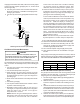
A closed return duct system must be used, with the return duct
connected to the furnace. NOTE: Ductwork must never be at-
tached to the back of the furnace. For upflow installations requir-
ing 1800 CFM or more, use either two side returns or bottom
return or a combination of side and bottom. Flexible joints may be