
GCVM96 & GMVM96 Installation Instructions

32
• Gas piping must be supported external to the furnace
cabinet so that the weight of the gas line does not distort
the burner rack, manifold or gas valve.
• Use black iron or steel pipe and fittings for building piping.
Where possible, use new pipe that is properly chamfered,
reamed, and free of burrs and chips. If old pipe is used,
be sure it is clean and free of rust, scale, burrs, chips, and
old pipe joint compound.
• Use pipe joint compound on male threads ONLY. Always
use pipe joint compound (pipe dope) that is APPROVED
FOR ALL GASES. DO NOT apply compound to the first
two threads.
• Use ground joint unions.
• Install a drip leg to trap dirt and moisture before it can enter
the gas valve. The drip leg must be a minimum of three
inches long.
• A line pressure test port is provided on the gas valve. If
desired, install a 1/8" NPT pipe plug fitting, accessible for
test gage connection, immediately upstream of the gas
supply connection to the furnace.
• Always use a back-up wrench when making the connection
to the gas valve to keep it from turning. The orientation of
the gas valve on the manifold must be maintained as shipped
from the factory. Maximum torque for the gas valve
connection is 375 in-lbs; excessive over-tightening may
damage the gas valve.
• Install a manual shutoff valve between the gas meter and
unit within six feet of the unit. If a union is installed, the
union must be downstream of the manual shutoff valve,
between the shutoff valve and the furnace.
• Tighten all joints securely.
• Connection method must be in compliance with all local
and national codes. US: National Fuel Gas Code
(NFGC) NFPA 54-2012/ANSI Z223.1-2012 and the
Installation Standards, Warm Air Heating and Air
Conditioning Systems ANSI/NFPA 90B.
In Canada, CANADA: National Standard of Canada,
Natural Gas and Propane Installation Code
(NSCNGPIC) CSA B149.1-2010.
Connect the furnace to the building piping by one of the
following methods:
– Rigid metallic pipe and fittings.
– Semi-rigid metallic tubing and metallic fittings.
Aluminum alloy tubing must not be used in exterior
locations. In order to seal the grommet cabinet
penetration, rigid pipe must be used to reach the
outside of the cabinet. A semi-rigid connector to the
gas piping may be used from there.
• Use listed gas appliance connectors in accordance with
their instructions. Connectors must be fully in the same
room as the furnace.
• Protect connectors and semirigid tubing against physical
and thermal damage when installed. Ensure aluminum-
alloy tubing and connectors are coated to protect against
external corrosion when in contact with masonry, plaster,
or insulation, or subjected to repeated wetting by liquids
such as water (except rain water), detergents, or sewage.
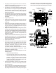
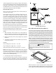
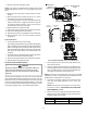
Gas Piping Connections
MANUAL
SHUT OFF VALVE
(UPSTREAM FROM
PIPE UNION)
GROMMET
IN STANDARD
GAS LINE HOLE
GAS LINE
PLUG IN
GAS LINE
HOLE
HEIGHT REQUIRED
BY LOCAL CODE
PIPE
UNION
DRIP LEG
MANIFOLD
BURNERSGAS VALVE
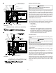
ALTERNATE
UNION
LOCATION
PLUG IN
A
LT ER N ATE
GAS LINE
HOLE
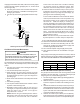
DRIP LEG
BURNERS
GAS VALVE