
GCVM96 & GMVM96 Installation Instructions

31
call for humidity. The integrated control module electronic air
cleaner terminals (EAC) are energized with 115 volts whenever
the circulator blower is energized.
24 VOLT HUMIDIFIER
A 24 volt humidifier can be powered by feeding one of the
HUM terminals with a field installed wire from the R terminal
or by connecting to the NO side of the low fire pressure
switch.
G
AS
S
UPPLY
AND
P
IPING
The furnace rating plate includes the approved furnace gas input
rating and gas types. The furnace must be equipped to operate on
the type of gas applied. This includes any conversion kits required
for alternate fuels and/or high altitude.
CAUTION
T
O
PREVEN T
UNRELIABLE
OPERATION
OR
EQU IP MENT
DAM AGE
,
THE
INLET
GAS
SUPPLY
PRESSURE
MUST
BE
AS
SP ECIF IED
ON
THE
UNIT
RATING
PLATE
WITH
ALL
OTHER
HOUSEHOLD
GAS
FIRED
APPLIANCES
OPERATING
.
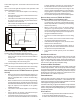
Inlet gas supply pressures must be maintained within the ranges
specified in the following table. The supply pressure must be
constant and available with all other household gas fired appli-
ances operating. The minimum gas supply pressure must be
maintained to prevent unreliable ignition. The maximum must not
be exceeded to prevent unit overfiring.
Natural Gas Minimum: 4.5" w.c. Maximum: 10.0" w.c.
Propane Gas Minimum: 11.0" w.c. Maximum: 13.0" w.c.
Inlet Gas Supply Pressure
HIGH A LTITUDE D ERATE
In some areas the gas supplier may artificially derate the gas in
an effort to compensate for the effects of altitude. If the gas is
artificially derated, the appropriate orifice size must be deter-
mined based upon the BTU/ft
3
content of the derated gas and the
altitude. Refer to the National Fuel Gas Code, NFPA 54/ANSI
Z223.1 or CAN/CSA B149.1 in Canada, and information pro-
vided by the gas supplier to determine the proper orifice size.
PROPANE G AS CONVERSION
WARNING
P
OSSIBLE
PROPERTY
DAMA GE
,
PERSONAL
INJURY
OR
DEATH
MAY
OCCUR
IF
THE
CO R RE C T
CONVERSIO N
KIT S
ARE
NOT
INSTALLED
.T
HE
APPROPRIATE
KITS
MUST
BE
APPLIED
TO
ENSURE
SAFE
AND
PROPER
FURNACE
OPERATION
.A
LL
CO N VE R SIONS
MUST
BE
PERFORMED
BY
A
QUA LIFIED
INSTALLER
OR
SERVICE
AGENCY
.
As shipped, this unit is configured for natural gas. The appropri-
ate manufacturer’s propane gas conversion kit, must be applied
for propane gas installations. Refer to the Propane Gas and/or
High Altitude Installations for details.
Consult the furnace Specification Sheet for a listing of appro-
priate kits. The indicated kits must be used to insure safe and
proper furnace operation. All conversions must be performed by
a qualified installer, or service agency.
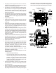
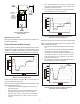
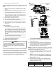
GAS VALVE
This unit is equipped with a 24 volt gas valve which modulates by
pneumatic linkage to the combustion air blower. Taps for mea-
suring the gas supply pressure and manifold pressure are provided
on the valve. This is a non-convertible, non-adjustable gas valve
equipped for natural gas.
The gas valve has a manual ON/OFF control located on the valve
itself. This control may be set only to the “ON” or “OFF” position.
Refer to the lighting instructions label or the Startup Procedure &
Adjustment section of this manual for use of this control during
start up and shut down periods.
GAS PIPING CONNECTIONS
T
O
AVOID
POSSIBLE
UNSATISFACTORY
OPERATION
OF
EQUIPMEN T
DAMAGE
DUE
TO
UND ER FIR IN G
OR
EQU IP MENT
,
USE
THE
PROPER
SIZE
OF
NATU RAL
/
PROPANE
GAS
PIPING
NEEDED
WHEN
RUNNING
PIPE
FROM
THE
METER
/
TAN K
TO
THE
FURNACE
.
WARNING
The gas piping supplying the furnace must be properly sized based
on the gas flow required, specific gravity of the gas, and length of
the run. The gas line installation must comply with local codes, or
in their absence, with the latest edition of the National Fuel Gas
Code, NFPA 54/ANSI Z223.1 or CAN/CSA B149.1 in Canada.
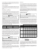
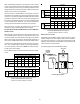
Natural Gas Capacity of Pipe In Cubic Feet of Gas Per Hour (CFH)
Nominal ½¾11¼1½22½
Actual ID: 0.622 0.824 1.049 1.380 1.610 2.067 2.469
Length (ft)
10 170 360 678 1390 2090 4020 6400
20 118 247 466 957 1430 2760 4400
30 95 199 374 768 1150 2220 3530
40 81 170 320 657 985 1900 3020
50 72 151 284 583 873 1680 2680
60 65 1370 257 528 791 1520 2430
70 60 126 237 486 728 1400 2230
80 56 117 220 452 677 1300 2080
90 52 110 207 424 635 1220 1950
100 50 104 195 400 600 1160 1840
125 44 92 173 355 532 1020 1630
150 40 83 157 322 482 928 1480
175 37 77 144 296 443 854 1360
200 34 71 134 275 412 794 1270
250 30 63 119 244 366 704 1120
Capacity in Cubic Feet of Gas per Hour
This chart refers to natural gas with an inlet pressure of less than 2 psi and a pressure
drop of 0.5" W.C. Specific gravity is 0.60.
Pipe Size (in.)
CFH = BTUH Furnace Input
Heating Valve of Gas (BTU/Cubic Foot)
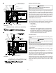
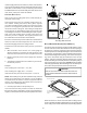
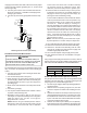
To connect the furnace to the building’s gas piping, the installer
must supply a ground joint union, drip leg, manual shutoff valve,
and line and fittings to connect to gas valve. In some cases, the
installer may also need to supply a transition piece from 1/2" pipe
to a larger pipe size.
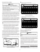
The following stipulations apply when connecting gas piping. Re-
fer to Gas Piping Connections figure for typical gas line connec-
tions to the furnace.