
GCVM96 & GMVM96 Installation Instructions

30
To use a single-stage thermostat, turn off power to the furnace,
move the thermostat selection DIP switch to the OFF position.
Turn power back on. Refer to the DIP switch chart in this
manual.
24 VOLT DEHUMIDISTAT WIRING
The optional usage of a dehumidistat allows the furnace’s circula-
tor blower to operate at a slightly lower speed (85% of desired
speed) during a combined thermostat call for cooling and dehu-
midistat call for dehumidification. This can be done through an
independent dehumidistat or through a thermostat’s DEHUM ter-
minal (if available). This lower blower speed enhances dehumidi-
fication of the conditioned air as it passes through the AC coil.
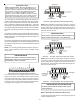
For proper function, a dehumidistat applied to this furnace must
operate on 24 VAC and utilize a switch which opens on humidity
rise. Refer to the “Thermostat Wiring Diagrams” figure for
additional wiring details.
To install/connect a dehumidistat:
1. Turn OFF power to furnace.
2. Secure the dehumidistat neutral wire (typically the white
lead) to the terminal marked “DEHUM” on the furnace
integrated control module.
3. Secure the dehumidistat hot wire (typically the black lead)
to the terminal marked “R” on the furnace integrated control
module.
4. Secure the dehumidistat ground wire (typically the green
lead) to the ground screw on the furnace junction box.
NOTE: Ground wire may not be present on all
dehumidistats.
5. If the condenser is a straight cooling unit, install a
jumper from Y1 to 0 on the furnace board.
6. Turn ON power to furnace.
To enable the dehumidify function on the integrated control mod-
ule, set the dehumidification ENABLE DIP switch from OFF to
ON.
Once the switch is set, the dehumidify function is enabled during
a combination call for cooling (T-Stat) and dehumidification
(DEHUM-Stat). Refer to the DIP switch chart in the back sec-
tion of this manual.
FOSSIL FUEL APPLICATIONS
This furnace can be used in conjunction with a heat pump in a
fossil fuel application. A fossil fuel application refers to a com-
bined gas furnace and heat pump installation which uses an out-
door temperature sensor to determine the most cost efficient means
of heating (heat pump or gas furnace).
A heat pump thermostat with three stages of heat is required to
properly use a two-stage furnace in conjunction with a heat pump.
Refer to the fossil fuel kit (AFE18-60A) installation instructions
for additional thermostat requirements.
Strictly follow the wiring guidelines in the fossil fuel kit installation
instructions. All furnace connections must be made to the fur-
nace control board and the “FURNACE” terminal strip on the
fossil fuel control board.
LINE VOLTAGE ACCESSORIES (ELECTRONIC AIR CLEANER
AND
HUMIDIFIER)
HIGHVOL TAGE!
T
O
AVOID
PERSONAL
INJU R Y
OR
DEATH
DUE
TO
ELECT R ICAL
SHOCK
,
DISCO NNECT
ELECT R ICAL
POWER
BEFORE
SER V ICING
OR
CHANGING
ANY
ELECT R ICAL
WIRING
.
WARNING
The furnace control board is equipped with line voltage acces-
sory terminals for controlling power to an electronic air cleaner.
The accessory load specifications are as follows. (The furnace
control board also has a set of dry contacts for humidifier
connection.)
Humidifier 1.0 Amp maximum at 120 VAC
Electronic Air Cleaner 1.0 Amp maximum at 120 VAC
Turn OFF power to the furnace before installing any accessories.
Follow the humidifier or air cleaner manufacturers’ instructions
for locating, mounting, grounding, and controlling these accesso-
ries. Accessory wiring connections are to be made through the
1/4" quick connect terminals provided on the furnace integrated
control module. The Electronic air cleaner hot terminal is iden-
tified as EAC. It is necessary to remove the protective tab
on the board cover to access the EAC Terminal. The EAC
neutral terminal is identified as NEUTRAL. A line voltage
humidifier may be connected between one of the HUM con-
tacts and NEUTRAL. The other HUM contact must be fed
from the L1 terminal.
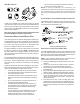
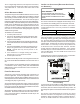
All field wiring must conform to applicable codes. Connections
should be made as shown in the following figure.
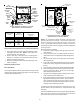
AUX OUT
AUX IN
L1
NEUTRAL
Accessories Wiring
If it is necessary for the installer to supply additional line voltage
wiring to the inside of the furnace, the wiring must conform to all
local codes, and have a minimum temperature rating of 105°C. All
line voltage wire splices must be made inside the furnace junction
box.
The furnace control board HUM (dry contacts) are closed
whenever the inducer is energized in a non-communicating
installation. When used with a CTK02** communicating ther-
mostat, the HUM terminals are closed whenever there is a