
GCVM96 & GMVM96 Installation Instructions

29
‐
HEATSET‐UPDIPSWITC H DIP
SWITCH
#13MUST
BE
SET
TO
MATCH
THERMOSTAT
TYPE
.T
O
USE
THE
CTK01
COM MUNICATIN G
THERMOSTAT
,
SWITCH
#13
MUST
BE
SET
TO
ON
POSITION
.T
HIS
IS
ALSO
THE
CO RRECT
SETTING
FOR
A
NON
‐
COMMUNICATING
2‐
STAGE
THERMOSTAT
.T
O
USE
CTK02**
OR
CTK03**
MODULATING
THERMOSTAT
,
CHECK
TO
MAKE
SURE
SWITCH
#13
IS
IN
THE
OFF
POSITION
(
FACTOR Y
POSITION
).T
HIS
IS
ALSO
THE
CO RRECT
POSITION
WHEN
USING
A
NON
‐
COMMUNICATING
SINGLE
‐
STAGE
THERMOSTAT
.
DIP
DIP
IMPORTANT NOTE
As a two-stage non-communicating furnace, the furnace inte-
grated control module provides terminals for both “W1” and “W2”,
and “Y1” and “Y2” thermostat connections. This allows the fur-
nace to support the following system applications: ‘Two-Stage
Heating Only’, ‘Two-Stage Heating with Single Stage Cooling’, and
‘Two-Stage Heating with Two-Stage Cooling’. Refer to the follow-
ing figures for proper connections to the integrated control mod-
ule.
Low voltage connections can be made through either the right or
left side panel. Thermostat wiring entrance holes are located in the
blower compartment. The following figure shows connections for a
“heat/cool system”.
This furnace is equipped with a 40 VA transformer to facilitate use
with most cooling equipment. Consult the wiring diagram, located
on the blower compartment door, for further details of 115 Volt and
24 Volt wiring.
NOTE: Use of cooling ramping profiles and dehum feature re-
quires a jumper between Y1 and O when a straight cooling
unit is used.
T
HERMOSTAT
“R”
REQUIRED
IF
OUTDOOR
UNIT
IS
EQU IPPE D
WITH
A
C
OMFORT
A
LERT
™
MODULE
OR
IF
THE
OUTDOOR
UNIT
IS
A
PART
OF
THE
C
OMFORT
N
ET
™
FAM ILY
OF
EQU IP MENT
.
IMPORTANT NOTE
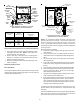
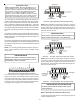
AUX
DEHUM
W2
C
1
Y1
2
R
W1
Y2
G
O
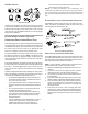
24 V THERMOSTAT CONNECTIONS
Low Voltage Connections with Auxiliary Terminals
The auxiliary contacts are shipped with a factory installed
jumper. As an option, the auxiliary contacts may be wired to
a normally closed float switch. In the event of open contacts,
the gas heat and cooling will be disabled until the condition is
corrected. These are 24 volt terminals powered internally, do
not apply another voltage source to these terminals.
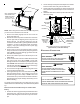
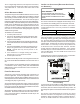
THERMOSTAT
R
Y C
NEU
Furnace Integrated
Control Module
Remote
Condensing Unit
(Single-Stage Cooling)
Dehumidistat
[Optional]
R
Thermostat - Single-Stage Heating with Single-Stage Cooling
NOTE: When installing a single stage cooling unit, it may be
necessary to jumper Y1 and Y2 on the furnace board to achieve
proper cooling CFM. Installer should check CFM charts to
determine this. Typical Cooling CFM is 350-400 CFM per ton,
based on outdoor unit size.
T
O
USE
A
SINGLE
‐
STAGE
H
EAT
T
HERMOSTAT
,DI P
SWITCH
#13
ON
THE
FURNACE
CONTROL
BOARD
MUST
BE
SET
TO
THE
OFF
POSITION
.
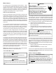
IMPORTANT NOTE
THERMOSTAT
R
Y C
Furnace Integrated
Control Module
Remote
Condensing Unit
(Single-Stage Cooling)
Dehumidistat
[Optional]
NEU
R
Thermostat - Two-Stage Heating with Single-Stage Cooling
NOTE: When installing a single stage cooling unit, it may be
necessary to jumper Y1 and Y2 on the furnace board to achieve
proper cooling CFM. Installer should check CFM charts to
determine this. Typical Cooling CFM is 350-400 CFM per ton,
based on outdoor unit size.
W1 W2
Y2
Furnace Integrated
Control Module
Remote
Condensing Unit
(Two-Stage Cooling)
Dehumidistat
[Optional]
Y2
NEU
W1 W2
Y2
Field installed jumper
to enable cooling
ramping profile when
using a straight
cooling unit.
Thermostat - Two-Stage Heating with Two-Stage Cooling
S
ET
DIP
SWITCH
#14
TO
ON
POSITION
WHEN
USING
A
2‐
STAGE
COOLING
THERMOSTAT
.
IMPORTANT NOTE (COOLING SETUP)
SINGLE-STAGE H EATING THERMOSTAT APPLICATION
A single-stage thermostat with only one heating stage may be
used to control this furnace.